VRMw Shim Retaining Ring FRU (contains 6 screws and pack of sandpaper)
1
5542958
-
Nonmagnetic Titanium Service Tool Kit, Large Set
1
5112581
-
B0 Power Supply Kit
1
2141701
-
STET tool
1
5431827
-
Consumables
Item
Quantity
Part number
Manufacturer
Sandpaper
As needed
-
-
Required conditions
Remove patient front end bell and patient support bridge from the magnet bore as described in appropriate procedures before starting work.
STET assembled and installed according to STET Operator Manual (5431810).
Table 1. Safety
Warning
Strong magnetic field
Ferrous materials can become dangerous projectiles in the presence of the magnetic field that the magnet produces.
Do not bring any ferrous tools or equipment into the magnet room.
Warning
Personal injury and equipment damage
Strong magnetic field.
When servicing any magnetic equipment, it is critically important that the service engineer consciously plan the path to be taken when moving highly ferrous devices in the magnet environment. The path should be as far from the magnet as practical. Safety Requirements:
The service path must allow for the dock to be moved along the ground a distance equal to that of the distance between the magnet and the foot-end of the patient table prior to being lifted vertically.
Two (2) MR safety trained personnel must be present at all times when servicing highly ferrous devices in the areas of magnetic fields.
When planning a service path, it is critical that the path be clear and sufficiently wide. Ensure that there are no trip hazards, obstacles, clutter, slippery surfaces or other items even partially restricting the path. If there are portable obstacles in a path, remove them from the area and replace them after the service action is completed. You must walk the path before beginning service to ensure that there is sufficient space through which to pass for yourself and the object being serviced.
About this task
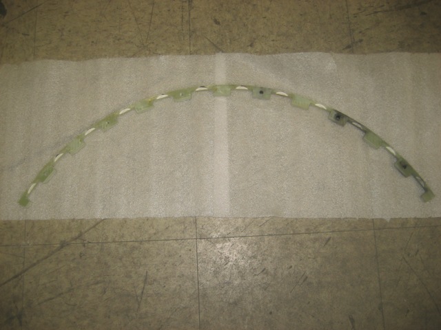
This procedure describes how to replace the shim retaining ring on the VRMw gradient coil while the magnet is ramped. The retaining ring is split into 3 segments, which can be replaced individually. The segments are split between shim trays 36 and 0, trays 12 and 13, and trays 24 and 25.
Figure 1. Shim retaining ring
Procedure
DANGER
Potential fatal injury
Before beginning this shim procedure, a second person (GE employee or contractor trained in safety requirements) must be present in the area in case of emergency.
All work assistants or observers must comply with the Work assistant/observer system requirements and certification subsection of the MR Magnet and Cryogen Manual.
Warning
Ferrous material hazard
The B0 power supply contains highly ferrous material. Ferrous materials can become dangerous projectiles within the magnetic field. Any field strength greater than 200G will forcibly attract the B0 power supply.
Do not bring the B0 power supply into the magnet room if the magnet is ramped.
Note: Induced current must be removed from the B0 coil before shimming the magnet. The B0 coil power supply kit is used to quench the induced currents in the B0 coil circuit. The B0 coil power supply is switchable from 115/230 VAC, 50/60 Hz. The B0 coil current must be removed whenever a shim drawer has been moved during the shimming process.
CAUTION
Strong magnetic field
Passive shim trays are highly ferrous. Personal injury or equipment damage may result if it is too close to the magnet.
Passive shim trays are highly ferrous. Heed all warnings in the Safety section.
Remove the passive shim trays from the gradient coil in the section where the ring segment is to be replaced.
Refer to the STET manual (5431810) for the shim tray removal process.
Notice
When you remove each tray, note the position number of that tray. Be sure to return each tray to the correct slot to avoid changing the shim of the magnet.
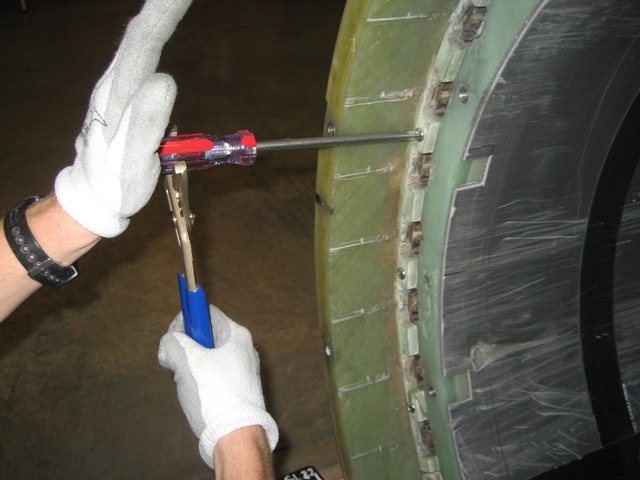
Using non-ferrous Phillips screwdriver and non-ferrous channel lock pliers, remove the 6 stainless mounting screws on the segment of the ring to be replaced.
You may need to tap on the screw heads to break the Loctite bond before you are able to remove them.
Figure 2. Removing stainless mounting screws
Pry loose and take out the broken ring segment. Start prying from the end of the segment to help break the epoxy bond.
Using sandpaper, clean the mounting surfaces on the gradient coil of any resin fragments to ensure a good fit of the ring segment (especially the mounting surface on the inner surface of the outer gradient coil).
Replace the broken ring segment with the new one.
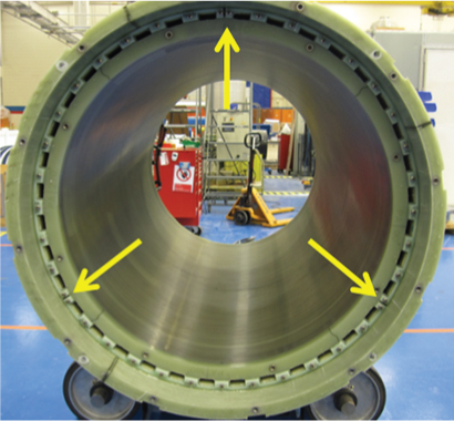
Figure 3. VRMw gradient coil shim retaining ring
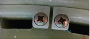
Secure each ring segment to the coil with (11 off) thread cutting screws (2162974-13) and (2 off) thread cutting screws (2162974-12) at both end of the ring.
Figure 4. Secure each ring segment
Safely re-install all passive shim trays. Be sure to return each tray to the correct slot to avoid changing the shim of the magnet.
Finalization
De-install STET as described in the STET Operator Manual (5431810).
Re-install the bridge and front end bell.
Connect the B0 coil power supply output cable to P304-1 on the magnet connector box.
Notice
Make sure the red switch under the power supply matches the input source (115 or 230 VAC).
Connect the B0 coil power supply input cable between the power supply and the voltage source.
Press the B0 coil power supply switch (the switch is spring-loaded) and hold for one minute.
The LED lights to indicate the power supply is supplying output current.
Wait for three minutes for the magnet to recover before performing LVShim.

 Note: Induced current must be removed from the B0 coil before shimming the magnet. The B0 coil power supply kit is used to quench the induced currents in the B0 coil circuit. The B0 coil power supply is switchable from 115/230 VAC, 50/60 Hz. The B0 coil current must be removed whenever a shim drawer has been moved during the shimming process.