
- SIGNA™ Hero 3.0T Service Methods
- 5852800-8EN Revision 1.0
- 00000018WIA3091D230GYZ
- id_156682111.13
- Jan 26, 2022 3:41:24 PM
VRMw manifold replacement
Prerequisites
| Personnel requirements | |||
|---|---|---|---|
| Required persons | Preliminary requirements | Procedure | Finalization |
| 1 | - | 8 hours | - |
| Tools and test equipment | |||
|---|---|---|---|
| Item | Quantity | Part number | Manufacturer |
| Safety Glasses | 1 for each person | - | - |
| Authorized Personnel Floor Sign (included with Safety Signage Kit 46-258770G4) | 1 | 2289812 | - |
| Nonmagnetic Titanium Service Tool Kit, Large Set | 1 | 5112581 | - |
| 5 Gallon Pail | 1 | 2239133 | - |
| Dispenser of 100 #6005 Large N-DEX Nitrile Disposable Gloves Best #6005L | 1 | 46-194427P400 | - |
| Consumables | |||
|---|---|---|---|
| Item | Quantity | Part number | Manufacturer |
| Coolant (1 Gallon Container) (See Required Conditions) | 15 | 5174313 | - |
| Coolant Fluid (5 Gallon Container) (See Required Conditions) | 3 | 5174313-2 | - |
| Coolant Manifold Replacement Kit | 1 |
See FRU Manual | - |
| Replacement parts | |||
|---|---|---|---|
| Item | Quantity | Part number | Manufacturer |
| VRMw Manifold | 1 |
Refer to FRU manual | - |
| Required conditions |
|---|
|
Approximately 4 gallons of coolant fluid is needed for each manifold replacement. FEs will decide which type of container to order. |
|
Power to the ISC is turned off and the LOTO procedures are implemented. |
|
Remove the body coil. |
| ||||||||||||
VRMw coil water removal
Procedure
- Note: Nitrile Gloves must be worn when performing coolant removal.Note: Follow customers procedure for proper disposal of coolant.Turn off the valve in coolant supply line at the service end of the magnet.
Figure 1. Turn off the valve 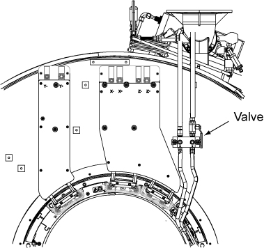
- Put an empty tank close to the magnet service-end to accept discharge coolant.
Figure 2. Draining manifold supply 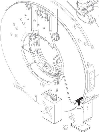
Old manifold removal
Procedure
- Remove the five cable ties that are securing the manifolds. (See Figure 3.)
Figure 3. Cable ties 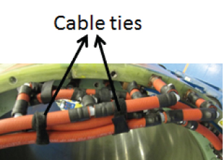
- Note: A non-magnetic side cutter is required to cut heat shrink.Using a non-magnet knife, carefully cut open the heat shrinks at the manifold-to-inner coil connections making sure not to cut the temperature sensor and wire when removing the heat shrink. (See Figure 4.)
Figure 4. Removing heat shrink 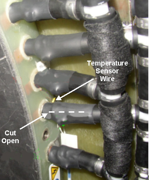
Once the hose clamp is open or pushed off the copper tube terminal, disconnect the manifold hose from the tube terminal.Notice 
New manifold installation
Procedure
- Take the VRMw Manifold Coolant Supply (5500297) and assemble it on the coil. (See Figure 5 for corresponding hoses and coil locations.) Make sure an 18.5 stainless steel hose clamp (5339948) and a 35mm long piece of heat shrink (5322136) are inserted on each manifold leg before pushing the hoses into position, and make sure that all hose clamps are in a similar orientation.
Figure 5. VRMw manifold coolant supply 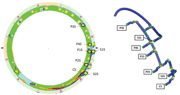
- Make sure the manifold supply assembly is in the correct position. (See Figure 6.)
Figure 6. Manifold coolant supply 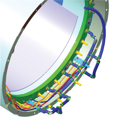
- Take VRMw Manifold Coolant Return (5500298) and assemble it on the coil. Make sure an 18.5 stainless steel hose clamp (5339948) and a 35mm long piece of heat shrink (5322136) are inserted on each manifold leg before pushing the hoses into position, and make sure that all hose clamps are in a similar orientation. (See Figure 7 for corresponding hoses and coil locations.)
Figure 7. VRMw manifold coolant return 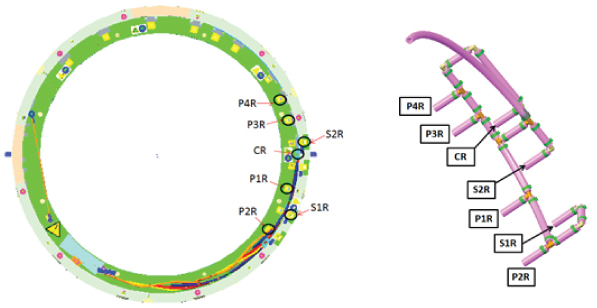
- Make sure the VRMw Manifold Coolant Return is on the correct position. (See Figure 8.)
Figure 8. Manifold coolant return 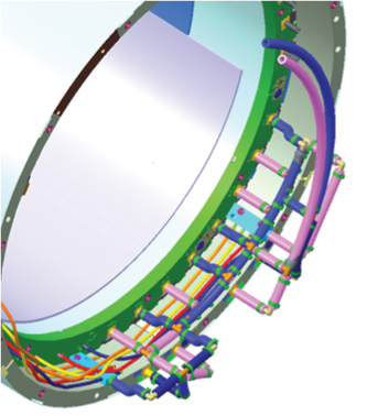
- Tighten the hose with five cable ties in below locations. (See Figure 9.)
Figure 9. Cable ties 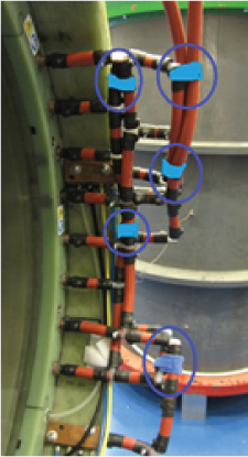
Finalization
Procedure
- Restore Body Coil by reverse order of removal.
- Remove the LOTO for the ISC.
- Refer to the ICC Hose and Valve Inspection, Coolant Fill, and Coolant Leak Check to add coolant to the GCU reservoir, turn on the heat exchanger pumps, and check the coolant system for leaks. The volume added should be close to that of the discharged coolant.
- Restore magnet front and rear end bells by reverse order of removal.
- Do a check scanto ensure the system is functioning correctly.