
- SIGNA™ Hero 3.0T Service Methods
- 5852800-8EN Revision 1.0
- 00000018WIA305EEE20GYZ
- id_131062883.17
- Oct 28, 2021 11:36:51 AM
Body Coil Tuning
Prerequisites
| Required persons | Preliminary requirements | Procedure | Finalization |
|---|---|---|---|
| 1 | - | - | - |
| Item | Quantity | Effectivity | Part number | Manufacturer |
|---|---|---|---|---|
| USB Memory | 1 | - | - | - |
| USB Mouse (For Network Analyzer operation) | 1 | - | - | - |
| Network Analyzer Service Tool Kit | 1 | - |
, 5336593-3, or 5336593-4 | - |
| Body Loader w/ Sphere Phantom | 1 | - |
2371511 | - |
| FOAM SUPPORT ECMT AND PHANTOM | 1 | - |
5554839 | - |
| ||||||||||||
| Condition | Reference | Effectivity |
|---|---|---|
|
Body Coil Isolation is done. | - | - |
|
System must be in scanning condition | - | - |
|
RF body coil temperature must be stable and match magnet room temperature | - | - |
About this task
Body Coil Tuning is performed by adjusting Variable Capacitors (VC1, VC2, VC3) to tune f1, f2, f3, and MagS21 according to the navigation of the Network Analyzer screen.
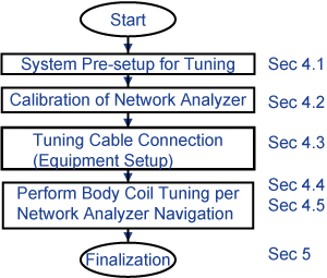
System Pre-setup for Tuning
Procedure
- Perform the following sub-steps to set up any body coil scan on scan window to setup driver module body BIAS mode.
- On the exciter/ref clock module located in the Pen or ISC cabinet, set the RF ENB switch down (Disable).
Figure 2. Exciter/ref clock module 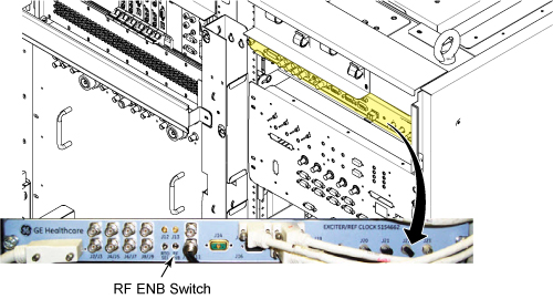
- On the exciter/ref clock module located in the Pen or ISC cabinet, set the RF ENB switch down (Disable).
- The body coil tuning driver is located behind the bridge cover. It will be used to tune the variable capacitor.
Figure 3. Remove the cover to access the tuning driver 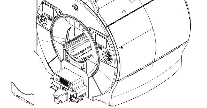
- Place body loader with phantom on the foam support, place them on the bridge, and push them into the magnet center so that front edge of body loader is 822mm (32.4 inches) away from the front edge of the bridge.
Figure 4. Body loader setup 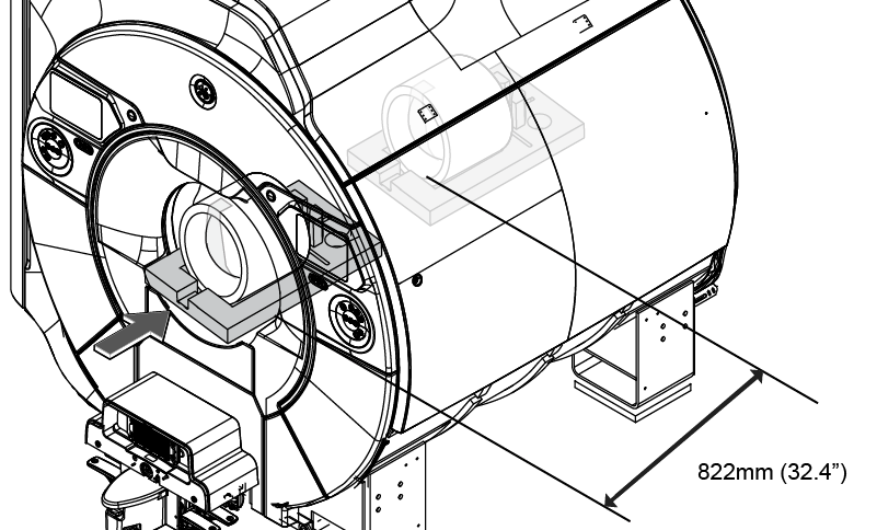 Note: Pioneer system is shown. This applies to both Pioneer and Hero systems.
Calibration of the network analyzer
Procedure
Connect Bias T at Port1 and Port2. Do not connect the Bias cable at this time.CAUTION 
Figure 5. Bias T installation 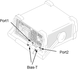
Notice  Note: Recommend to connect a mouse to one of the USB ports on the network analyzer.Power ON the network analyzer. If no power seen confirm AC power switch on rear of unit in 'I' position.
If not using the mouse, it is necessary to use hard key. For example, select [Menu] hardkey and then use arrow (<, >) hardkeys to navigate and highlight, and [ENTER] hardkey to select from menu.
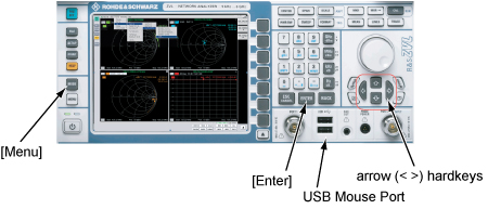
Figure 6. Power ON 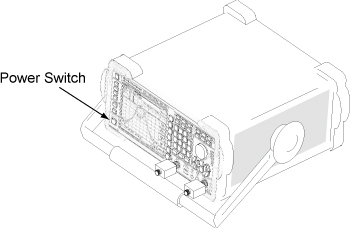
- If the network analyzer is not ready, start either the ZVL Analyzer (5336593-3) from the Windows screen, or the Vector Network Analyzer (5336593-4). (This step might not be needed.)
Figure 7. Start ZVL Analyzer (5336593-3) 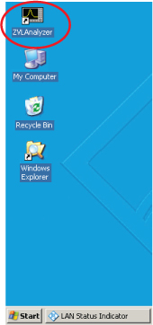
Figure 8. Start Vector Network Analyzer (5336593-4) 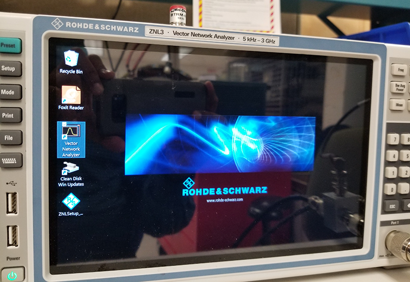
- For Vector Network Analyzer (5336593-4), do the following to change the Preset mode to Network Analyzer:
- Close the window.
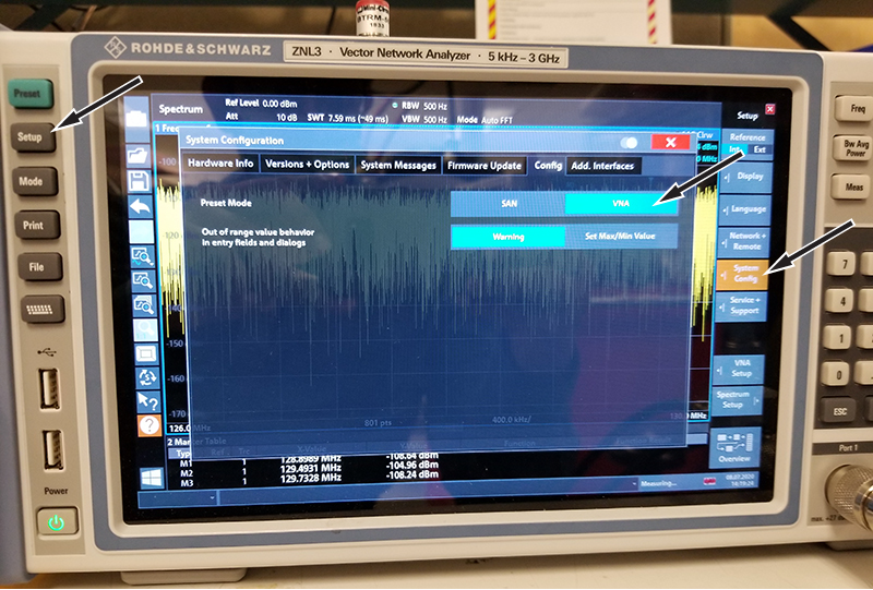
- Close the window.
- Select Pioneer 3T body coil tuning, based on your network analyzer:
Option Description For ZVL Analyzer (5336593-3) Select . Figure 9. Pioneer 3T Body Coil Tuning.lnk 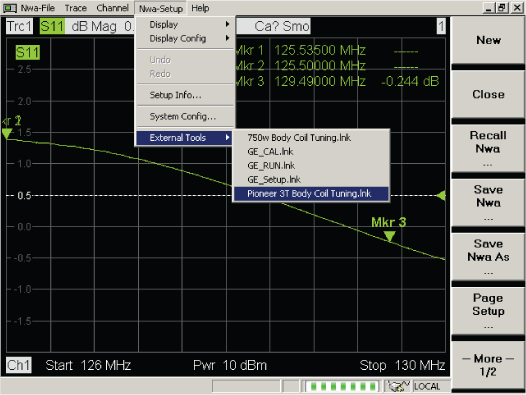
For Vector Network Analyzer (5336593-4) Select the Start menu, and then select Pioneer 3T Body Coil Tuning. Figure 10. Pioneer 3T Body Coil Tuning 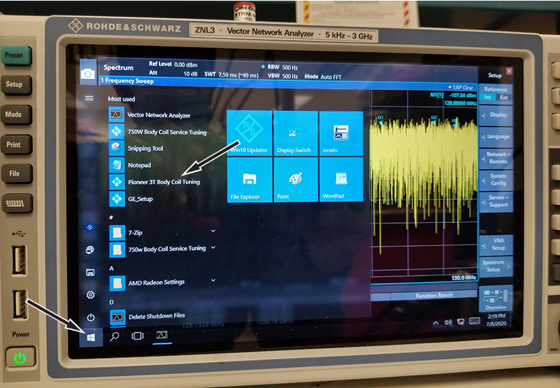
The following screen shows up. For button selection, proceed to Step 7.Notice 
Figure 11. Calibration start menu 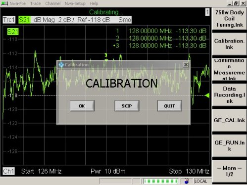
- Select button shown in Figure 11 per following instruction.
- If calibration of the network analyzer has already been done and the following conditions are satisfied, click [Skip] to skip the calibration and go to equipment setup.
-
The current setup is the same as last calibration.
-
It is less than 1 day since last calibration.
-
No other calibration has been run on network analyzer.
-
If [Skip] is clicked, the confirmation screen shown in Figure 12 comes up. Confirm the condition again and click [OK]. Then, go to Body coil tuning using network analyzer navigation.
-
If any condition is not satisfied, click [Quit] button, then press the blue Pre-Set hard-key button on front left side of unit, and start the tool again.
Figure 12. Confirmation screen 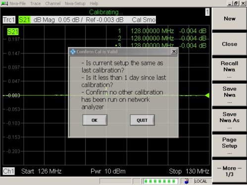
-
- If calibration of the network analyzer has already been done and the following conditions are satisfied, click [Skip] to skip the calibration and go to equipment setup.
- When [OK] is selected at Step 7, the following message comes up. Confirm that DC cable is not connected to Bias-Ts and click [OK].
Figure 13. Message 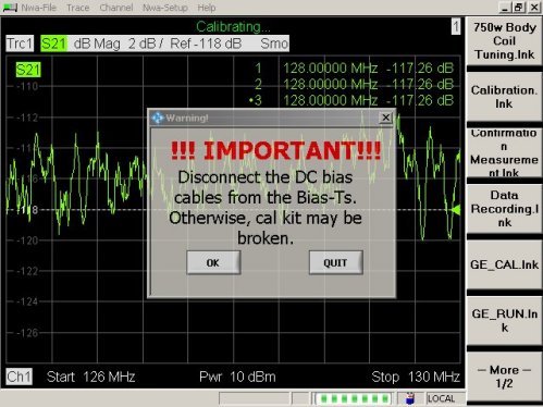
- Connect N(m) to N(m) coaxial cable to Bias T of Port1. Refer to Figure 14.
Figure 14. Cable Connection 1 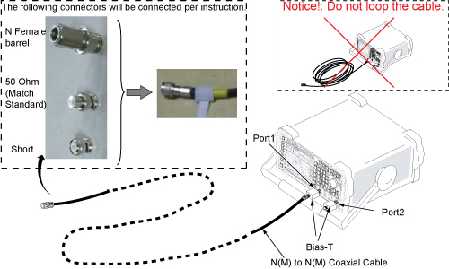 Note: Do not touch the cable ends and minimize human interaction during network analyzer calibration, as this can change the Impedance of the calibration setup.
Also it is best to not cross the cables, and route so that they are parallel and separated from each other as much as possible.
Note: It is recommended that the 50 ohm load (Match Standard) be measured with a DVM to confirm that it is operational (50 ohms +/- 5 ohms). Connecting it to end of BNC-f to BNC-f adapter or BNC-f to N-m adapter and measuring through opposite end of adapter sometimes provides most reliable electrical connection for measurement. - Connect female barrel and “BNC female to N male” to the end port 1 of the channel 1 cable. Do not attach any BNC 'Standard' connectors. Click [OK] when the following message is displayed. Do not make any changes until prompted.
Figure 15. Message for OPEN 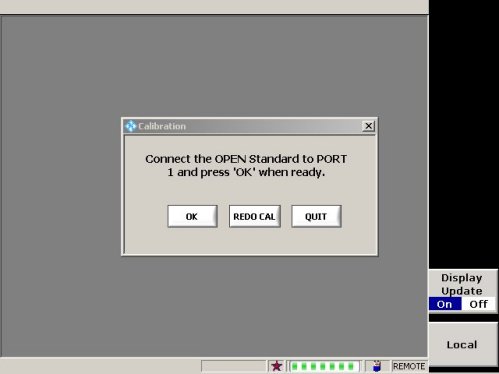 Note: It will take about 15 seconds to display next message after clicking [OK] .
 - Connect Short standard to “BNC female to N male” and click [OK] when the following message is displayed.
Figure 16. Message for SHORT 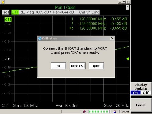
- Remove Short, connect 50 Ohm load standard and click [OK] when the following message is displayed.
Figure 17. Message for MATCH Standard (50 Ohm Load) 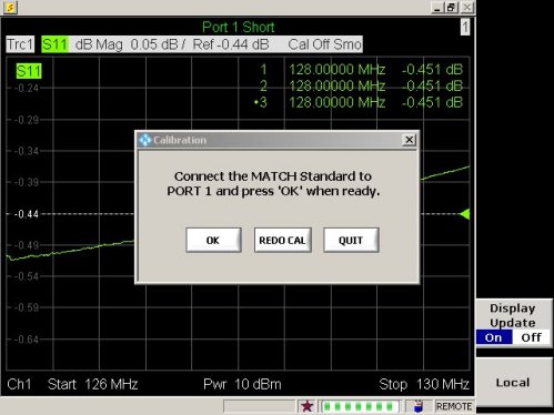
- Connect port 1 and port 2 cables through female barrel.
Figure 18. Cable Connection 2 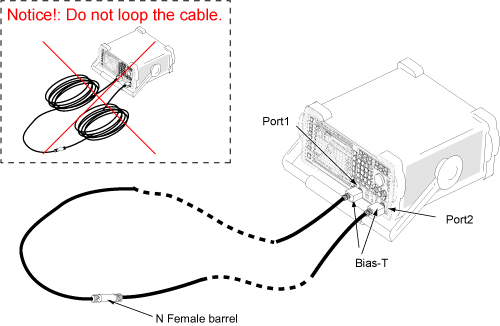
- Click [OK] when the following message is displayed. Calibration is complete.
Figure 19. Message for THROUGH Standard 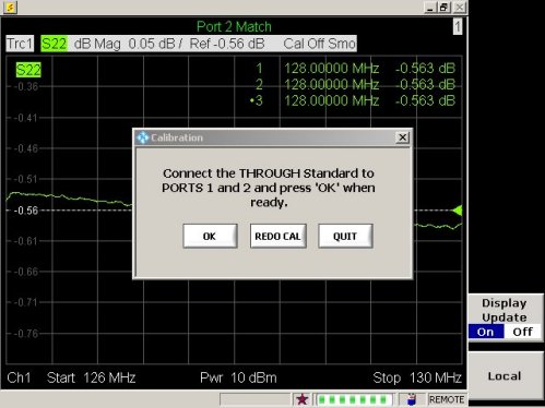
- Once calibration is completed, the following screen comes up. Proceed to “Tuning Cable Connection (Equipment Setup)” by referring to Tuning cable connection (Equipment setup). Keep Network Analyzer screen as it is during “Tuning Cable Connection (Equipment Setup)”.
Figure 20. Message for Equipment Setup 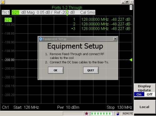
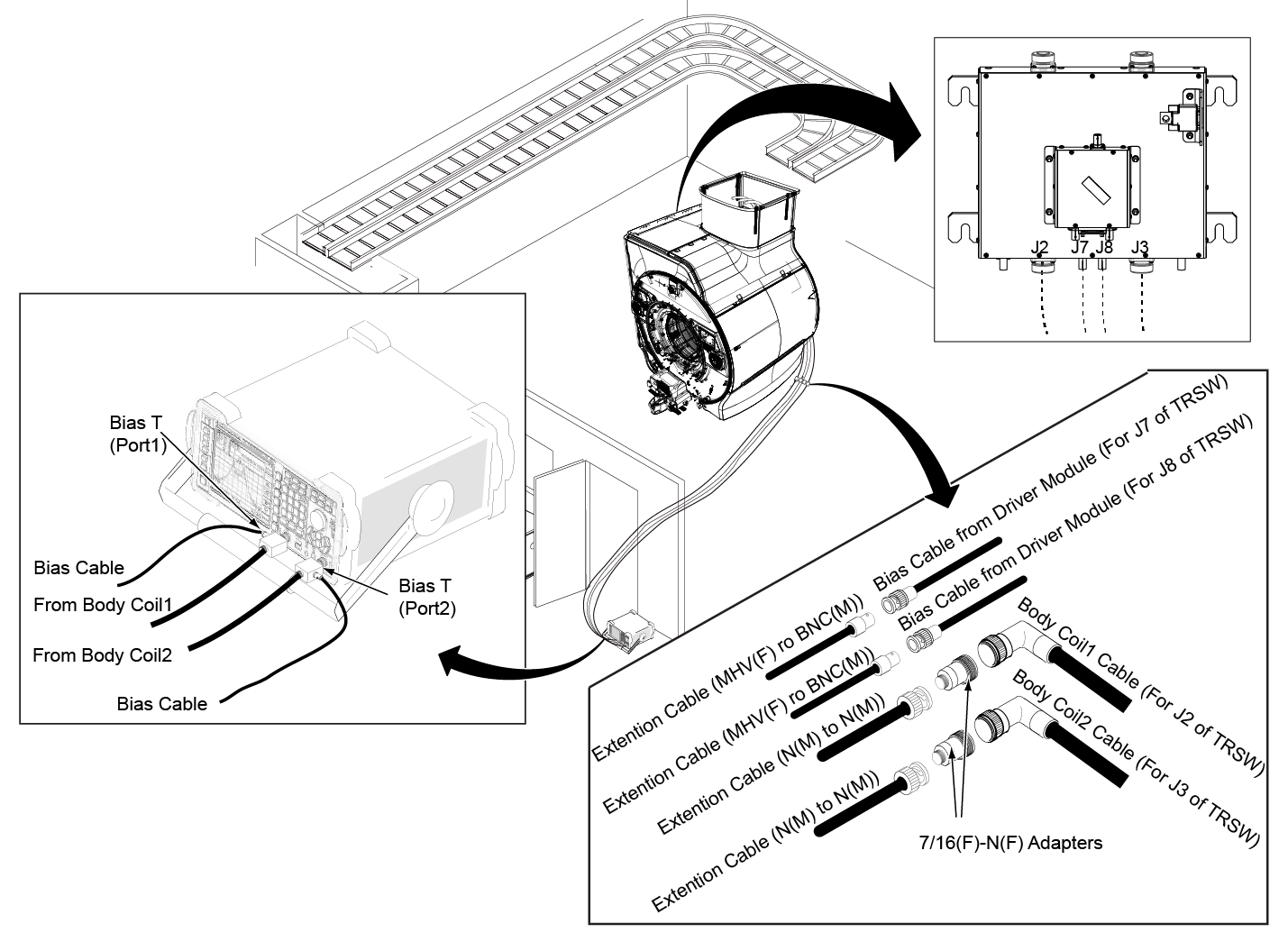
Tuning cable connection (Equipment setup)
Procedure
| Warning | |
|---|---|
Body coil tuning using network analyzer navigation
Procedure
- Once tuning cable connection (equipment setup) is completed, click [OK].
Figure 22. Message for equipment setup - Ch1 measurement will start. Click [OK] to record f1.
Figure 23. Message for Ch1 measurement 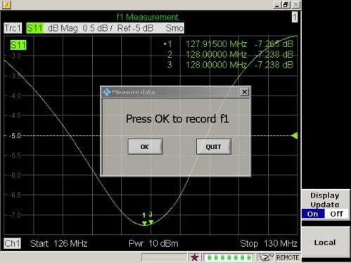 Note: In case the following screen comes up, it means S11 Magnitude is unusual.
Figure 24. Message for unusual S11 Magnitude 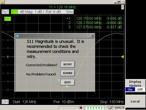
In this case, please check the following conditions.
-
The cradle is not located in the magnet bore.
-
Bridge is installed in the the magnet.
-
Phantom is setup correctly per the System Pre-setup for Tuning section.
-
Cables are connected correctly per System Pre-setup for Tuning section.
-
Driver module DD bias in 'Body' mode. (-13.6VDC unloaded. ~2.6VDC Loaded, Exact voltages not critical.)
Notice
Once problem is corrected, click [Retry]. If there is no problem for the condition above, click [Ignore].
-
- Ch2 measurement will start. Click [OK] to record f2.
Figure 25. Message for Ch2 measurement  Note: In case the following screen comes up, it means S22 Magnitude is unusual.
Figure 26. Message for unusual S22 Magnitude 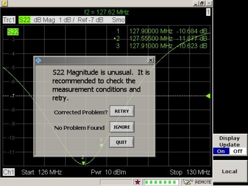
In this case, please check the following conditions.
-
Cradle is not located in the magnet bore.
-
Bridge is installed in the the magnet.
-
Phantom is setup correctly per System Pre-setup for Tuning section.
-
Cables are connected correctly per System Pre-setup for Tuning section.
-
Driver module DD bias in 'Body' mode. (-13.6VDC Unloaded, ~2.6VDC Loaded, Exact voltages not critical.)
Notice
Once problem is corrected, click on [Retry].
-
- From here, display on the network analyzer will navigate the operation. Follow the instruction shown in the display of the network analyzer.Note: If the body coil is within specification, a pop-up which is shown in Figure 36 will appear. You are done tuning.
-
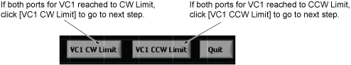
If VC1 CW or VC1 CCW is shown, turn VC1 using stick to tune f1 until [VC1 TUNED!] is displayed. Once [VC1 TUNED!] is displayed, click [OK] to go to next step.
Figure 27. Display 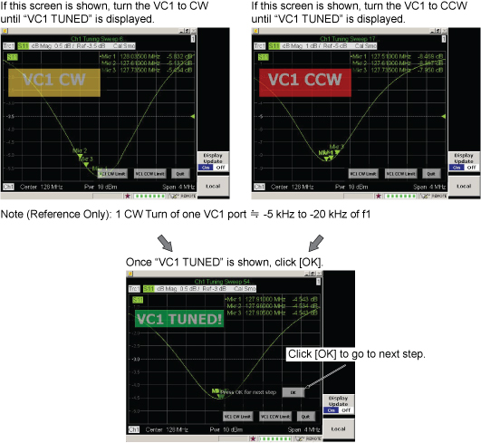
Figure 28. Tuning 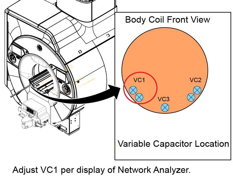 Note: There are two ports for VC1 and you can adjust either one. If the one reached to the limit, turn the other one for adjustment.
Notice -
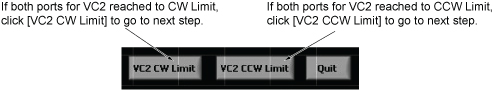
If VC2 CW or VC2 CCW is shown, turn VC2 using stick to tune f2 until [VC2 TUNED!] is displayed. Once [VC2 TUNED!] Is displayed, click [OK] to go to next step.
Figure 29. Display 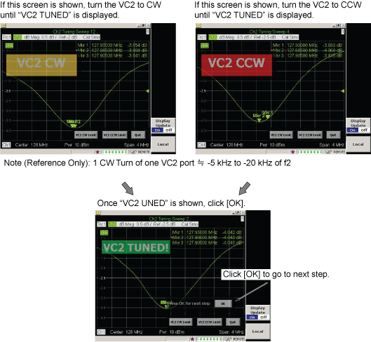
Figure 30. Tuning 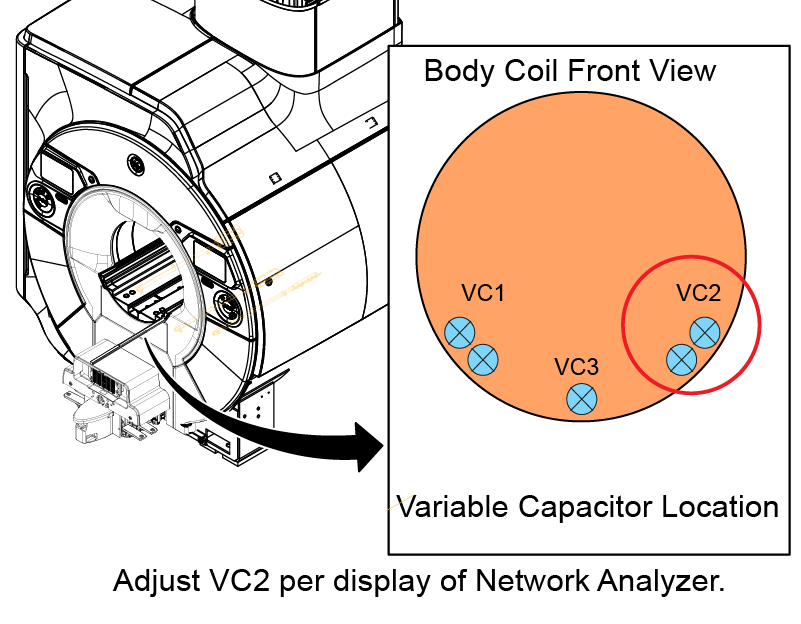 Note: There are two ports for VC2 and you can adjust either one. If the one reached to the limit, turn the other one for adjustment.
Notice -
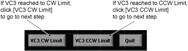
If VC3 CW or VC3 CCW is shown, turn VC3 using stick to tune f3 until [VC3 TUNED!] is displayed. Once [VC3 TUNED!] Is displayed, click [OK] to go to next step.
Notice Figure 31. Display 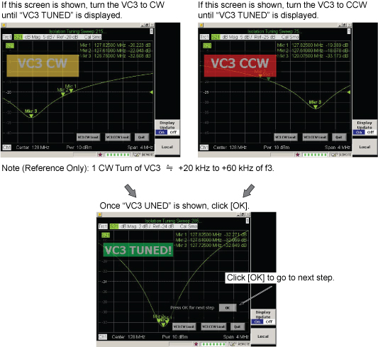
Figure 32. Tuning 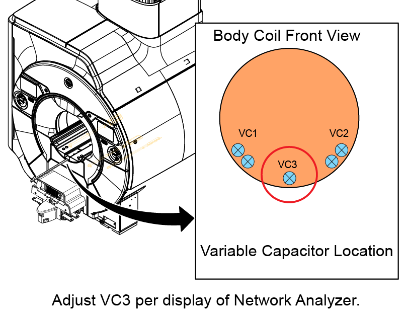
Notice Note: If VC3 Tuned does not display even though tuning is performed according to the displayed instruction, select [VC3 CW Limit] or [VC3 CCW Limit] and start VC1 tuning per displayed instruction. If the VC1 Tuning and VC2 tuning are completed properly, the dialog box shown in Figure 34 will display. Turn the VC3 to CCW limit according to the displayed instruction and select [Retry]. Then, VC3 adjustment will be available.Note: In case the following screen comes up, it means S11, S22, or S21 Magnitude is unusual.Figure 33. Message for unusual S11, S22, or S21 Magnitude 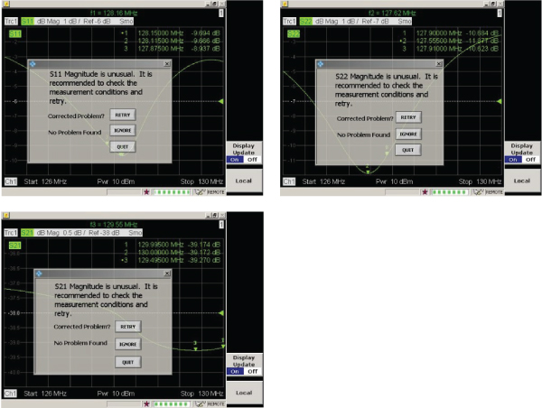
In this case, please check the following conditions.
-
The cradle is not located in the magnet bore.
-
The bridge is installed in the magnet.
-
Phantom is setup correctly per System Pre-setup for Tuning section.
-
Cables are connected correctly per System Pre-setup for Tuning section.
-
Driver module DD bias in 'Body' mode. Driver module DD bias in 'Body' mode. (-13.6VDC Unloaded, ~2.6VDC Loaded, exact voltages not critical.)
Notice Once problem is corrected, click on [Retry].
-
-
If you see the screen shown in Figure 34, turn the VC3 to CCW limit according to the displayed instruction and click [Retry] to start tuning.
Note: If you see this screen second time, turn the VC3 to CCW limit and click [Retry] and try again.If you see this screen three times or more, click [Quit]. It will navigate to troubleshooting.
Figure 34. RETRY or QUIT message 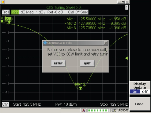
-
- Once the following screen comes up, click [OK] to start the calculation.
Figure 35. Record data screen 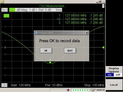
- Measured data is calculated and the result is shown on the display. Proceed per result as follows.
- Note: The measured data will be archived in the following directory of the network analyzer.Once the screen shown in Figure 36 is displayed, Body Coil tuning is completed. Go to #id_14939534__SL3911556-1178721.
-
C:\Program\Pioneer 3T Body Coil Tuning
-
File Name example: September 19, 2012 @ 5_35 PM Data.txt
-
Select ‘Firmware Exit’, ‘My Computer’ to save to USB memory stick.
Notice
Note: The value in following screen is an example. Check the Pass or fail result.Figure 36. Measured Data (All Pass) 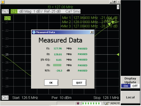
-
- If any of result is failed, following kind of screen shows up. Click [OK] and follow the navigation screen to perform more tuning.Note: The value in following screen is an example. Check the Pass or fail result.
Figure 37. Measured data (Failed) 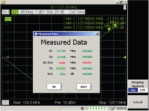
Troubleshooting
Procedure
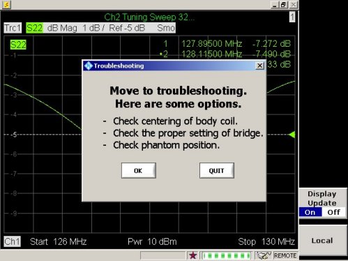
-
Perform Body Coil Isolation.
-
Confirm bridge alignment and height correct per installation manual.
-
Check phantom position.
-
Replace the body coil.
Finalization
Procedure
- On the Exciter/Ref Clock module located in the Pen or ISC cabinet, set the RF Enb switch up (Enable).
Figure 39. Exciter/ref clock module