
- SIGNA™ Hero 3.0T Service Methods
- 5852800-8EN Revision 1.0
- 00000018WIA30AF4450GYZ
- id_20221311.15
- Oct 11, 2021 6:31:29 PM
Removing the pedal link bar connector
Removes the pedal link bar connector that operates the foot pedal.
Prerequisites
| Personnel requirements | |||
|---|---|---|---|
| Required persons | Preliminary requirements | Procedure | Finalization |
| 1 | - | 10 minutes | - |
| Tools and test equipment | |||
|---|---|---|---|
| Item | Quantity | Part number | Manufacturer |
| Nonmagnetic Titanium Service Tool Kit, Small Set | 1 | 5113258 | - |
Procedure
- Lower the table lock safety bar. Lower the table and verify that all weight is resting on the lock bar.
Figure 1. Lock safety bar down 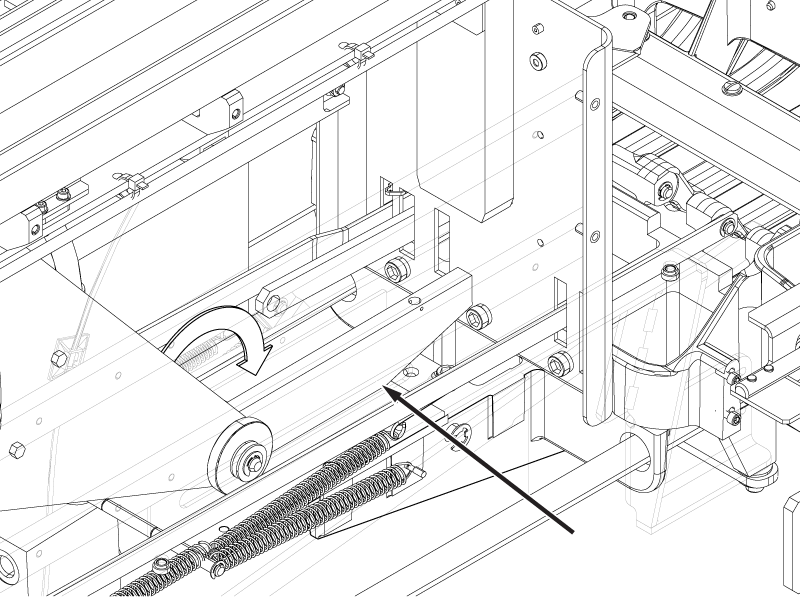
- Remove the spring attached to the pedal link bar connector at the rear of the patient table.Note: The spring is located between the Physiological Acquisition Controller and the table scissor jack.
Figure 2. Pedal link bar springs - right hand side view 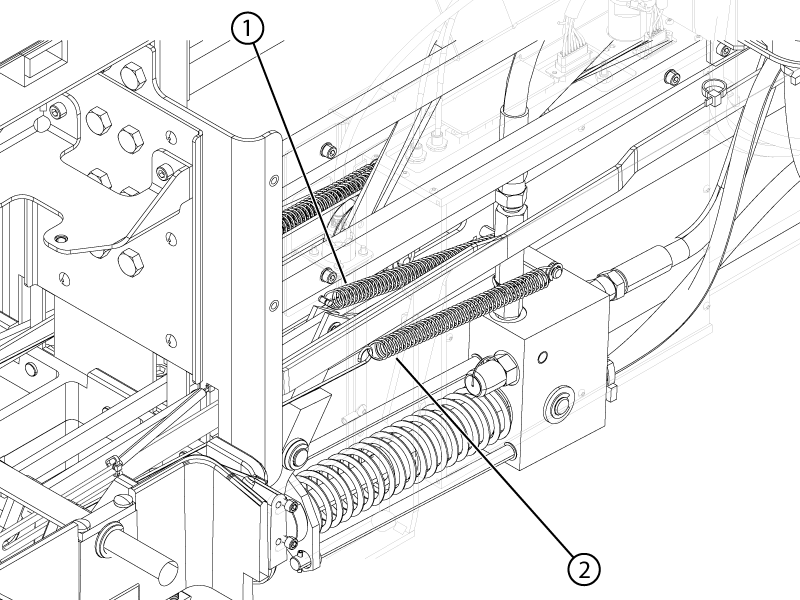
Figure 3. Pedal link bar springs - left hand side view 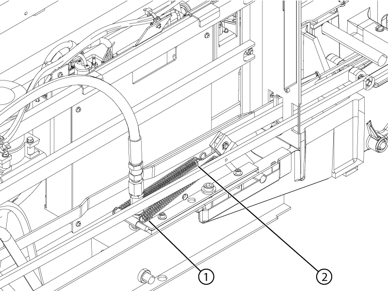
1 Electrical dock pedal link bar spring 2 Down pedal link bar spring - Remove the E-clips that secure the pedal link bar connectors to the Electrical Dock and Down pedals.
Figure 4. Pedal E-clips 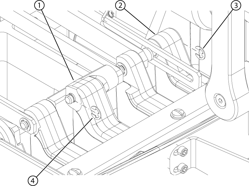
1 Electrical dock pedal 2 Down pedal 3 Down pedal E-clip 4 Electrical dock pedal E-clip - Remove the pin from the Down pedal link bar connector.Note: Removing the pin allows the down link to be pushed up for access to the Electrical Dock pin.Note: Press the Down pedal to access the pin.
Figure 5. Down pedal connector pin 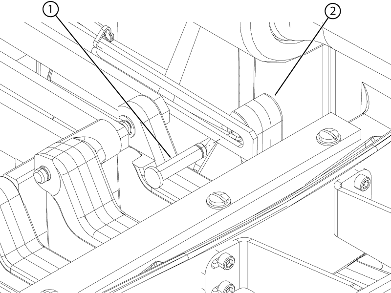
1 Pin 2 Down pedal - Pull the link down bar up to allow access to the pedal link bar connector. Push and remove the pin from the pedal link bar connector.
Figure 6. Pedal pin 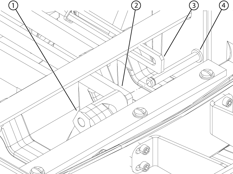
1 Electrical dock pedal 2 Electrical dock pedal link bar 3 Link down bar 4 Pin - Move the pedal link bar to access screws on the block lift. Remove the two screws securing the block lift to the pedal link bar connector. Remove the block lift.Note:
Save the two screws and the block lift for installation on the replacement pedal link bar connector.
Figure 7. Block lift 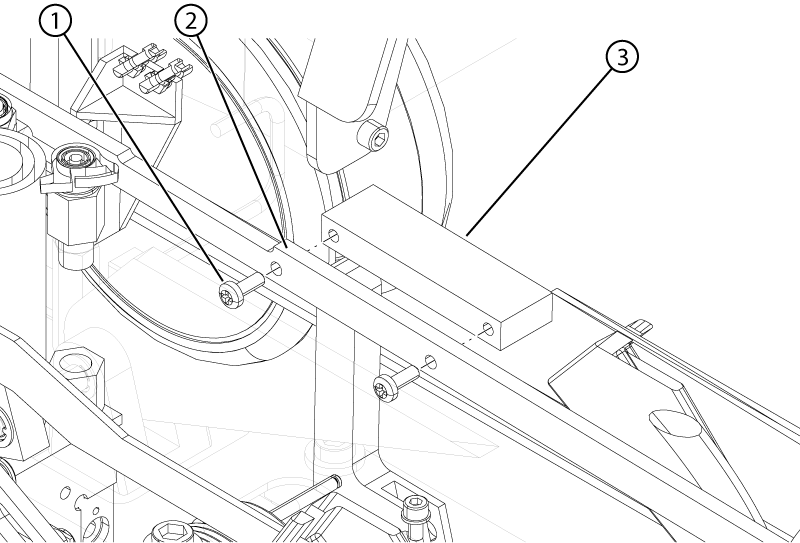
1 Screw 2 Pedal link bar 3 Block lift - Remove the three screws and three washers securing the rubber pedal stop to the table base.
Figure 8. Rubber pedal stop 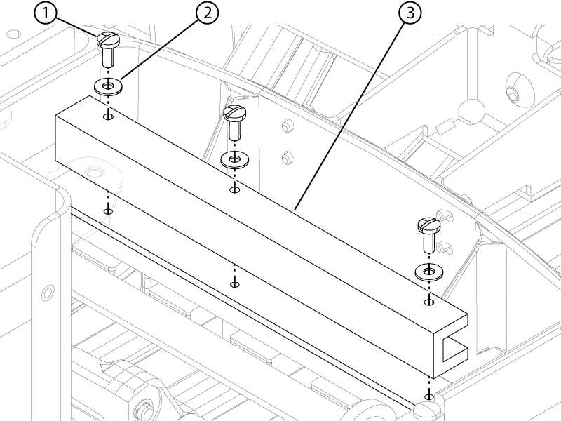
1 Screw 2 Washer 3 Rubber pedal stop - Remove the groove pin from the pedal link bar. Retain the pin for the replacement link bar.
Figure 9. Pedal link bar connector groove pin 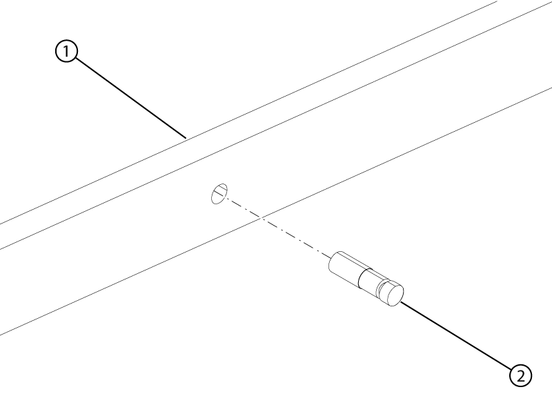
1 Pedal link bar connector 2 Groove pin