Installs the pedal link bar connector that operates the foot pedal.
Prerequisites
| Personnel requirements |
|---|
| Required persons | Preliminary requirements | Procedure | Finalization |
|---|
| 1 | - | 10 minutes | - |
| Tools and test equipment |
|---|
| Item | Quantity | Part number | Manufacturer |
|---|
| Nonmagnetic Titanium Service Tool Kit, Small Set | 1 | 5113258 | - |
Procedure
| CAUTION |
|---|
| Possible component damage The pedal link bar connector may be bent or damaged. Install the pin into the link bar carefully to avoid bending or damaging the link bar during pin installation. |
Install the groove pin from the removed pedal link bar connector into the new pedal link bar connector.
Figure 1. Pedal link bar connector groove pin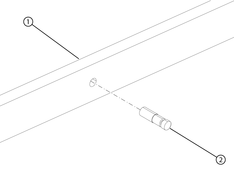
| 1 | Pedal link bar connector |
| 2 | Groove pin |
- Install the pedal link bar connector by sliding it under the table frame from the handle-end of the table.
- Install the rubber pedal stop onto the table base.
Figure 2. Rubber pedal stop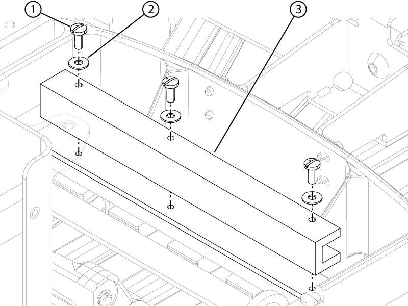
| 1 | Screw |
| 2 | Washer |
| 3 | Rubber pedal stop |
- Install the three screws and three washers securing the rubber pedal stop to the table base.
- Move the pedal link bar to access screws on the block lift. Install the two screws securing the block lift to the pedal link bar connector.
Figure 3. Block lift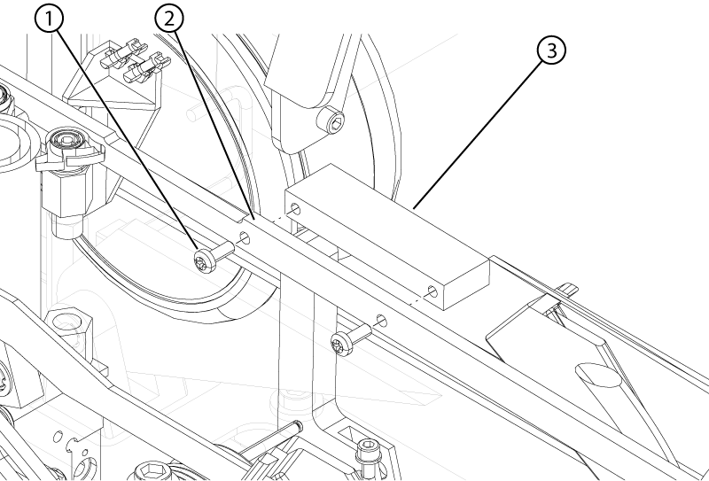
| 1 | Screw |
| 2 | Pedal link bar |
| 3 | Block lift |
- Pull the link down bar up to allow access the pedal link bar connector. Install the pin into the pedal link bar connector.
Figure 4. Pedal pin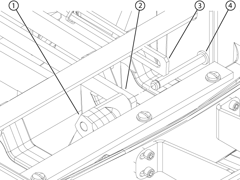
| 1 | Electrical dock pedal |
| 2 | Electrical dock pedal link bar |
| 3 | Link down bar |
| 4 | Pin |
- Install the pin into the Down pedal link bar connector.
Figure 5. Down pedal connector pin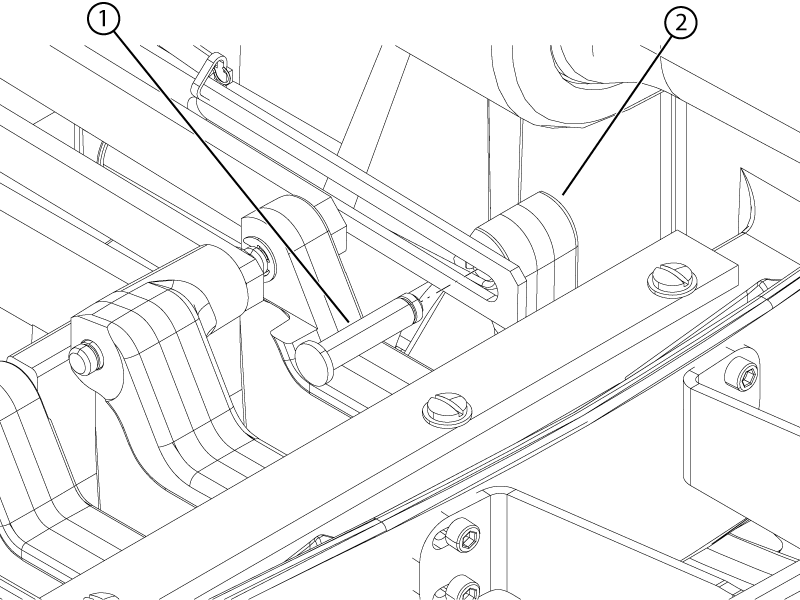
- Install the E-clips that secure the pedal link bar connectors to the Electrical Dock and Down pedals.
Figure 6. Pedal E-clips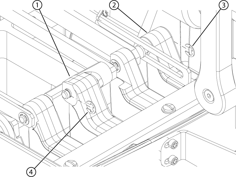
| 1 | Electrical dock pedal |
| 2 | Down pedal |
| 3 | Down pedal E-clip |
| 4 | Electrical dock pedal E-clip |
- Install the spring attached to the Down pedal link bar connector.
Note: The spring is located between the Physiological Acquisition Controller and the table scissor jack.
Figure 7. Pedal link bar springs - right hand side view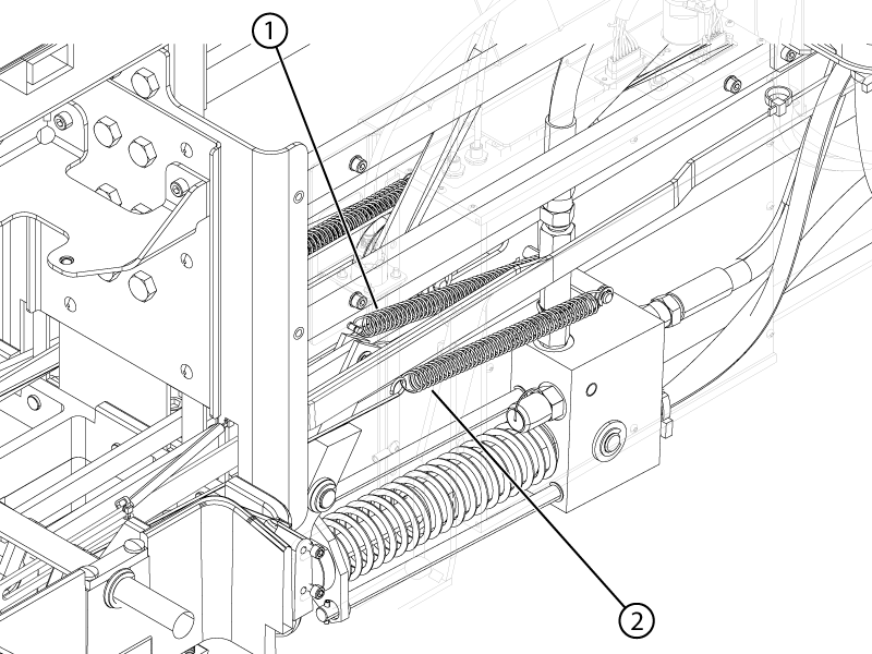
Figure 8. Pedal link bar springs - left hand side view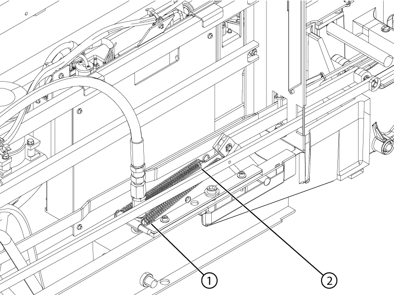
| 1 | Electrical dock pedal link bar spring |
| 2 | Down pedal link bar spring |
- Install the spring attached to the pedal link bar connector at the rear of the patient table.
- Raise the table so the weight is off of the lock bar. Raise the table lock safety bar.
