- SIGNA™ Hero 3.0T Service Methods
- 5852800-8EN Revision 1.0
- 00000018WIA30618530GYZ
- id_20112814.1
- Jul 13, 2021 4:16:32 PM
Removing the Integrated Control Engine (ICE)
Removing the Integrated Control Engine (ICE) from the System Cabinet.
Prerequisites
| Personnel requirements | |||
|---|---|---|---|
| Required persons | Preliminary requirements | Procedure | Finalization |
| 1 | - | 30 minutes | - |
| Tools and test equipment | |||
|---|---|---|---|
| Item | Quantity | Part number | Manufacturer |
| Nonmagnetic Titanium Service Tool Kit, Small Set | 1 Kit | 5113258 | - |
| Nonmagnetic Titanium Service Tool Kit, Large Set | 5112581 | - | |
Procedure
- Connect the Electrostatic Discharge (ESD) strap to the ESD bond point above the Direct Current Power Supply (DCPS) in the ISC and wear the ESD wrist band.
Figure 1. ESD wrist band 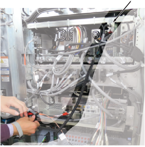
- Disconnect the ICE power cable from J1 of the ICE DCPS and the Ethernet cables from the switch.
Figure 2. Removing cables from the switch 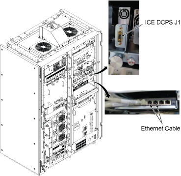
- Remove the ICE as follows:
- Carefully move the cables out of the way, and slide the ICE out.
Figure 3. Removing the ICE 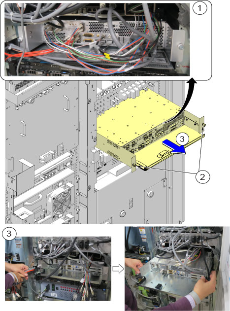
1 Disconnect all connectors from front panel 2 Remove the screws 3 Slide the ICE out
- Carefully move the cables out of the way, and slide the ICE out.
- Disconnect the PCIe cable (J51) from the ICE rear panel.
Figure 4. Disconnecting the PCIe cable 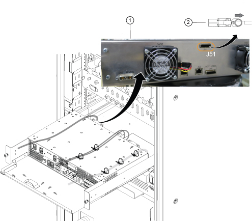
1 Rear view 2 Pull the ring to disconnect - Remove the cables from the rear panel as follows:
- Release all reusable tie wraps, and remove cables. (Lift up the latch and push the tie wrap to release it.)
- Disconnect two Ethernet cables (J53, J54) and the power cable (J52) from the ICE rear panel.
Figure 5. Ethernet cables (J53, J54) and power cable (J52) 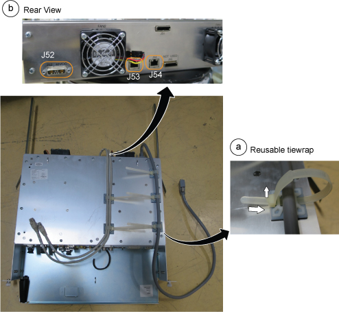
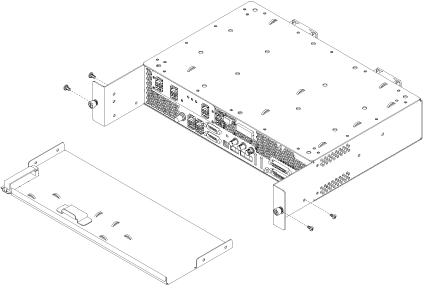
- Detach the slide rails from the ICE High Level Assembly (HLA) and install them to the new FRU.
Figure 6. Slide rails 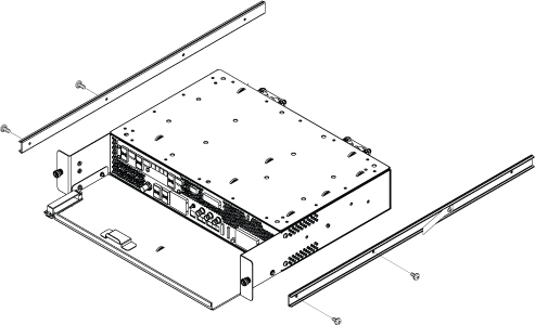 Note: When you install the slide rail on the side of the ICE, install the screw near the rear of the ICE in the hole shown below. This keeps the rail straight.
Figure 7. Screw installed through slide rail 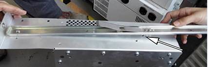
- Remove the ICE front plate and install it to the new FRU.
Figure 8. ICE front plate