
- SIGNA™ Hero 3.0T Service Methods
- 5852800-8EN Revision 1.0
- 00000018WIA30CF1E40GYZ
- id_20197052.18
- Oct 11, 2021 6:31:30 PM
Removing the hydraulic cylinder
Removes the hydraulic cylinder from a dockable patient table.
Procedure
Lower the table lock safety bar, then lower the table to make sure weight is resting on the safety bar.Warning 
Figure 1. Table lock safety bar 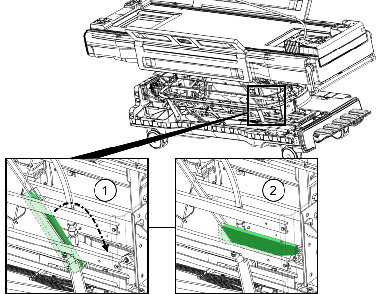
1 Safety bar up (unlocked) 2 Safety bar down (locked) - Use a long-handled, ball-end 3 mm Allen key to remove the hex screw from the anti-rotation collar at the top of the hydraulic cylinder, and then use a 4 mm Allen key to remove the two screws securing the upper bracket to the underside of the table.
Figure 2. Anti-rotation collar and upper bracket 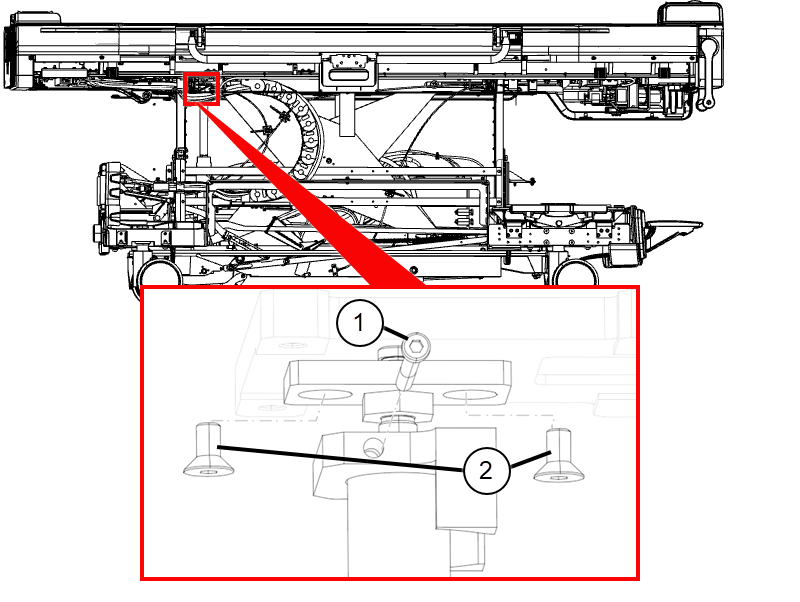
1 Anti-rotation collar screw 2 Upper bracket screws - While moving the table down valve to the rear of the table, pull down on the hydraulic cylinder until it is fully retracted.
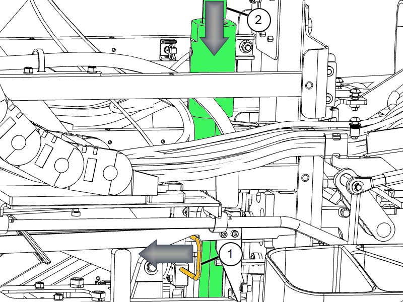
1 Table down valve 2 Hydraulic cylinder - Disconnect the table down valve actuator from the hydraulic cylinder by removing the attachment screw.
Figure 3. Table down valve actuator 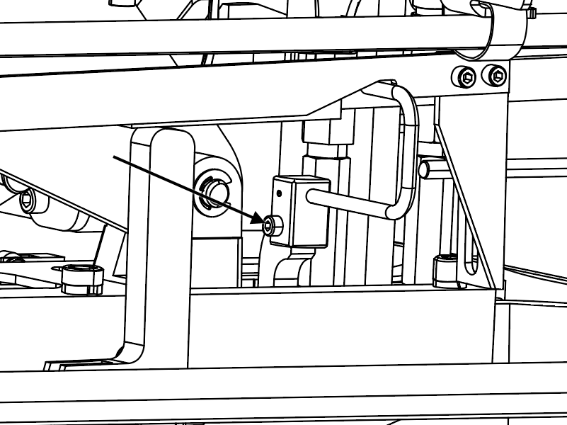
- Remove the e-clip, upper bracket, anti-rotation collar, and adjustment screw from the top of the cylinder, and retain the parts.
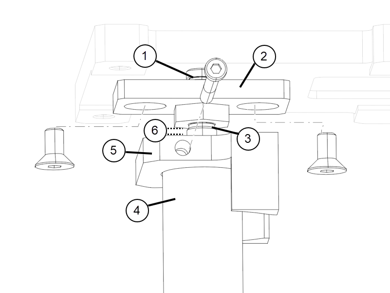
1 E-clip 2 Upper bracket 3 Adjustment screw 4 Hydraulic cylinder shaft 5 Anti-rotation collar 6 Distance between height adjustment screw nut and top of cylinder shaft