- SIGNA™ Hero 3.0T Service Methods
- 5852800-8EN Revision 1.0
- 00000018WIA30EF1E40GYZ
- id_20197072.15
- Oct 11, 2021 6:31:29 PM
Installing the hydraulic cylinder
Installs the hydraulic cylinder in a dockable patient table.
Procedure
- Apply anti-seize lubricant to the adjustment screw, and attach the adjustment screw, anti-rotation collar, upper bracket, and e-clip to the top of the replacement cylinder.
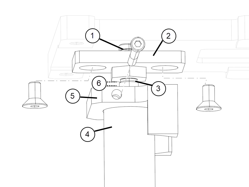
1 E-clip 2 Upper bracket 3 Adjustment screw 4 Hydraulic cylinder shaft 5 Anti-rotation collar 6 Distance between height adjustment screw nut and top of cylinder shaft Note: Make sure to set the distance between the height adjustment screw nut and the top of the cylinder shaft to the same measurement previously observed. - Reconnect the hydraulic lines to the base of the hydraulic cylinder. To help avoid leaks, use a new hose clamp to secure the low-pressure line.Note: To avoid obstruction of down link movement, carefully angle the low-pressure line hose clamp facing inward.
Figure 1. Low-pressure line hose clamp 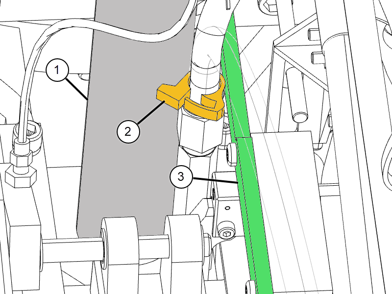
1 Hydraulic cylinder 2 Hose clamp 3 Down link - Attach the table down valve actuator to the hydraulic cylinder by inserting and tightening the attachment screw.
Figure 2. Hydraulic cylinder and attached down valve actuator 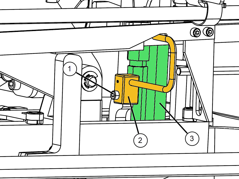
1 Screw 2 Table down valve actuator 3 Hydraulic cylinder - When top of cylinder reaches table top, reattach the upper bracket to the underside of the table, and then secure the anti-rotation collar.
Figure 3. Anti-rotation collar and upper bracket 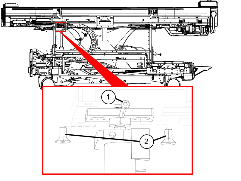
1 Anti-rotation collar screw 2 Upper bracket screws
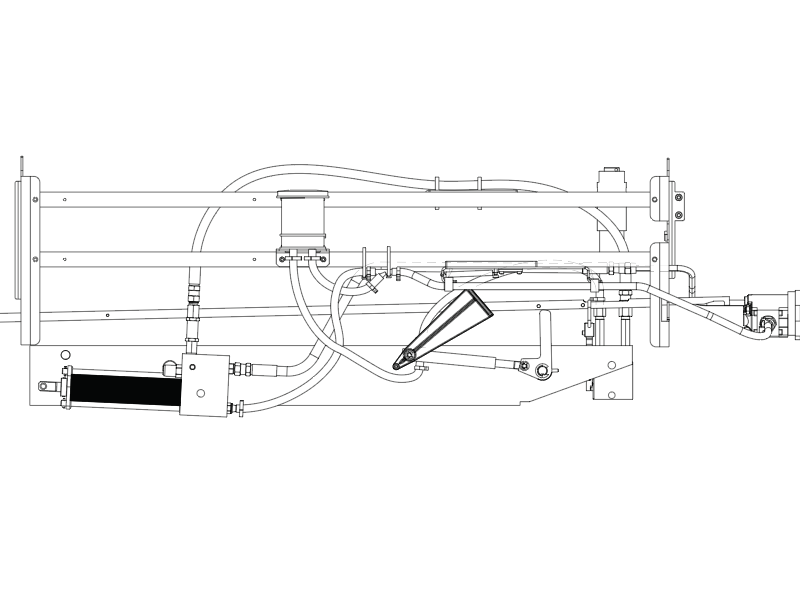
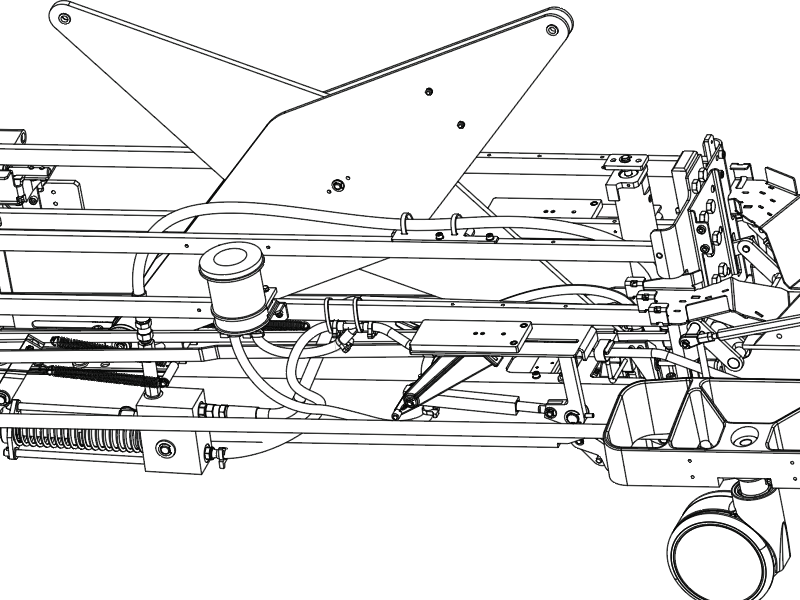
Finalization
To ensure unrestricted table movement and help avoid leaks, verify that all hydraulic lines are routed and secured appropriately, according to Figure 4 and Figure 5.