- SIGNA™ Hero 3.0T Service Methods
- 5852800-8EN Revision 1.0
- 00000018WIA30222E40GYZ
- id_20197431.13
- Apr 23, 2020 8:52:11 PM
Installing the dockable table rigibelt drive (actuator)
Installs the rigibelt drive into the dockable table tabletop.
Prerequisites
| Personnel requirements | |||
|---|---|---|---|
| Required persons | Preliminary requirements | Procedure | Finalization |
| 1 | - | 25 minutes | - |
| Tools and test equipment | |||
|---|---|---|---|
| Item | Quantity | Part number | Manufacturer |
| Nonmagnetic Titanium Service Tool Kit, Small Set | 1 | 5113258 | - |
| Pair: Cut-Resistant Gloves | 1 | - | - |
| Consumables | |||
|---|---|---|---|
| Item | Quantity | Part number | Manufacturer |
| Loctite #243 | As needed | 5415261-3 | - |
About this task
| CAUTION | |
|---|---|
Procedure
- Remove the protective heat shrink tubing from the rigibelt left and right side plates.
Figure 1. Rigibelt side plates 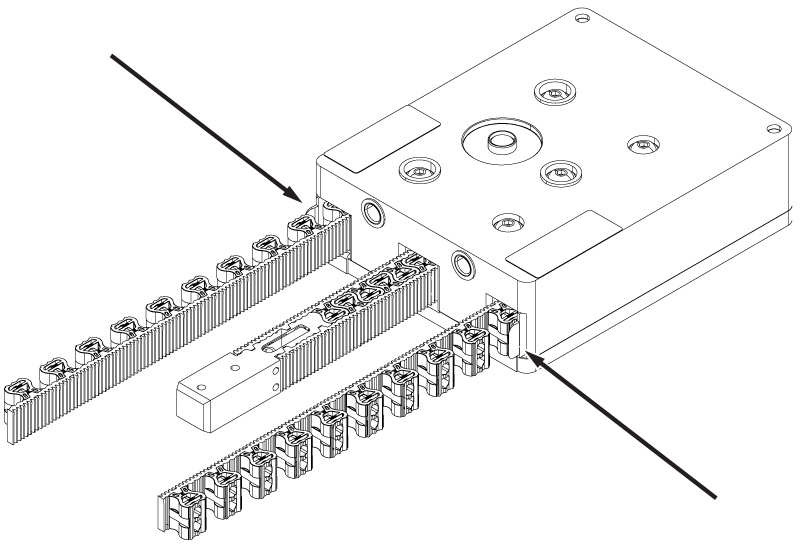
- Start the ends of the rigibelt into the tabletop rigibelt channels.
Figure 2. Rigibelt alignment 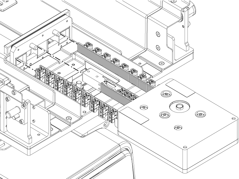
- Tilt the rear of the drive upwards while installing so the drive shaft moves over the rear bar of the tabletop.
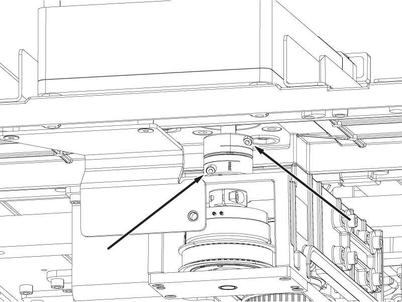
Figure 3. Rigibelt drive shaft 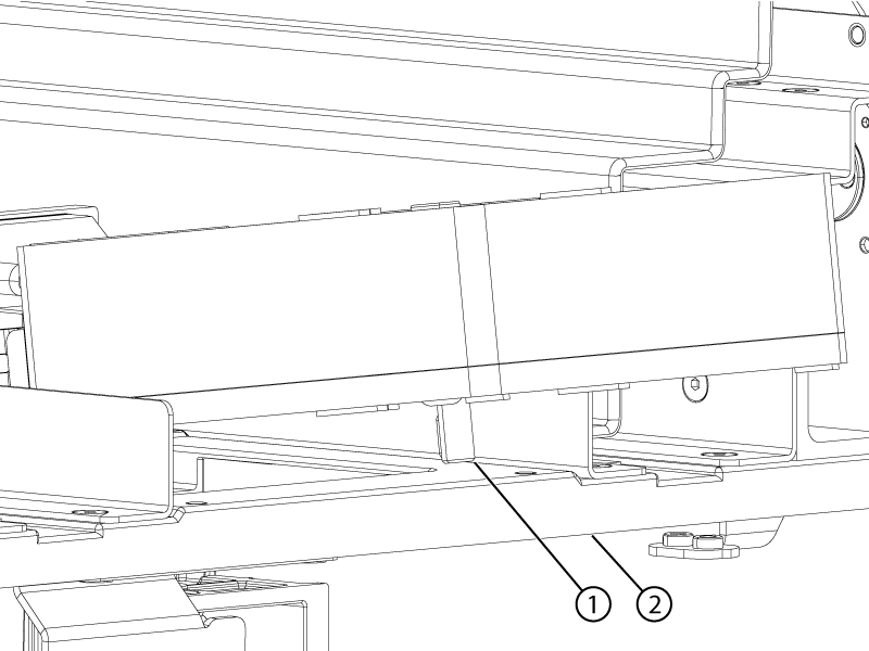
1 Rigibelt drive shaft 2 Table rear bar - When the drive shaft is past the bar, install the coupler onto the rigibelt drive shaft and slide it up fully onto the drive shaft. Do not tighten the coupler screws at this time.
Figure 4. Rigibelt coupler 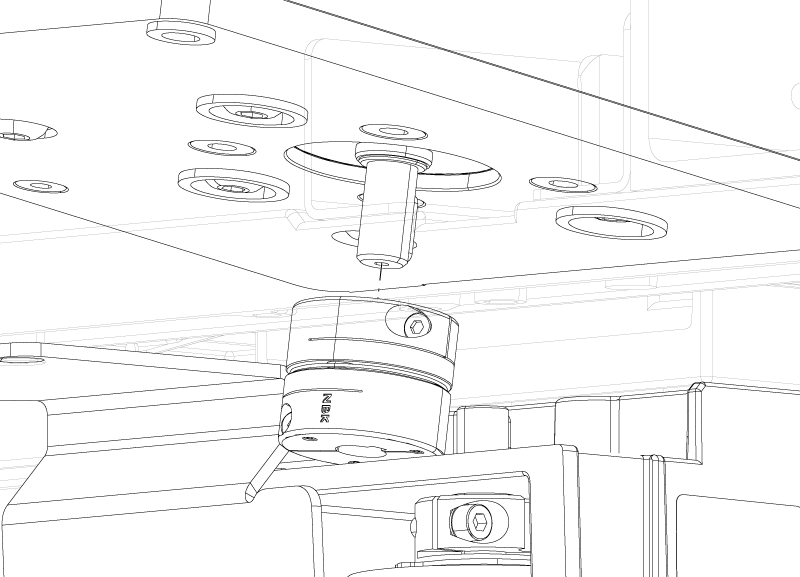
- Install the two screws securing the rigibelt drive to the tabletop.
Figure 5. Rigibelt drive screws 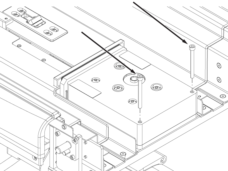
- Install the two screws securing the rigibelt to the rigibelt mounting block.Note: Move the rigibelt mounting block by moving the cradle in or out to align the mounting block screw holes with the rigibelt screw holes.
Figure 6. Rigibelt mounting screws 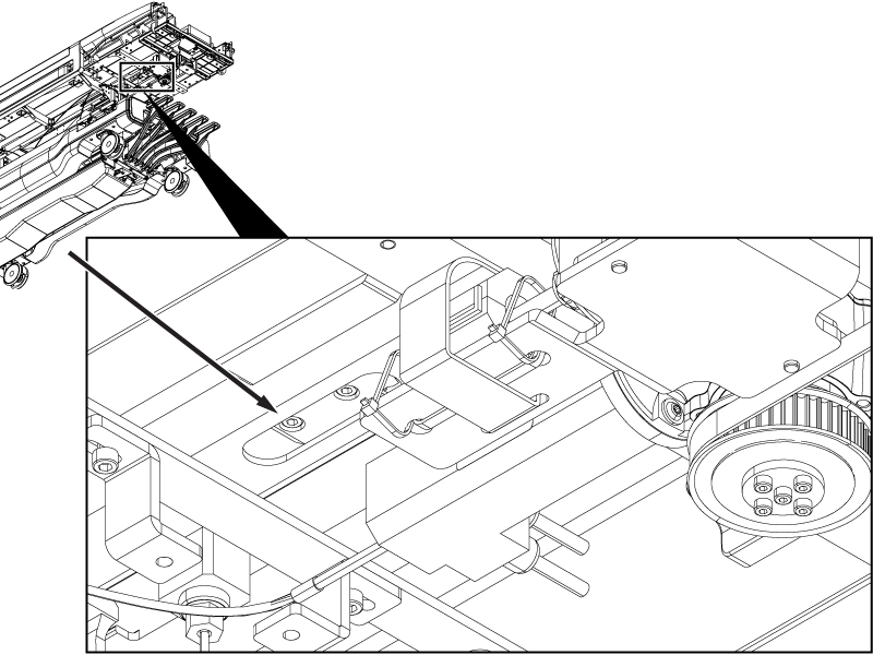
Figure 7. Rigibelt mounting block alignment 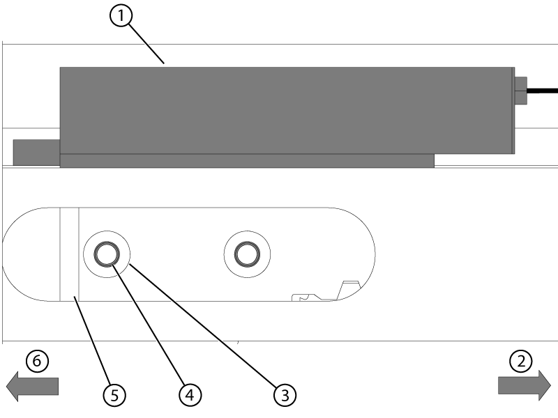
1 Rigibelt mounting block 2 Handle end of table 3 Rigibelt screw holes 4 Mounting block screw holes 5 Rigibelt 6 Bore end of table - Tighten the two screws securing the coupler to the drive shafts.
Figure 8. Rigibelt drive coupler screws