Removes the hydraulic rotary pump from the dockable table.
Prerequisites
Warning
Personal injury possibility
When doing maintenance on the table in its up position, severe personal injury can occur if the table is accidentally lowered during maintenance.
Make sure the lock safety bar is safely in place.
Warning
Ferrous material
The rotary pump's primary substance is steel and poses extremely dangerous projectile hazard if working in magnet room.
Make sure you are doing the procedure outside of the magnet room.
Procedure
Raise the patient table to the full up position.
Set the brake to keep the table stationary.
Figure 1. Caster brake
Lower the table lock safety bar to the locked position.
Note: Lower the table so its weight is resting on the lock bar.
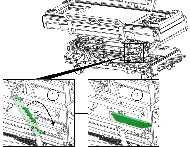
Figure 2. Lock safety bar
1
Safety bar up (unlocked)
2
Safety bar down (locked)
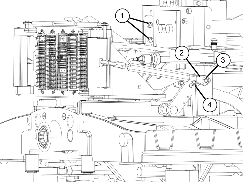
To remove the table frame connector assembly , do the following:
Remove the e-clip from the rod link on the right side of the table frame connector assembly, and slide the rod link off of the pin. Repeat this process on the left side of the assembly.
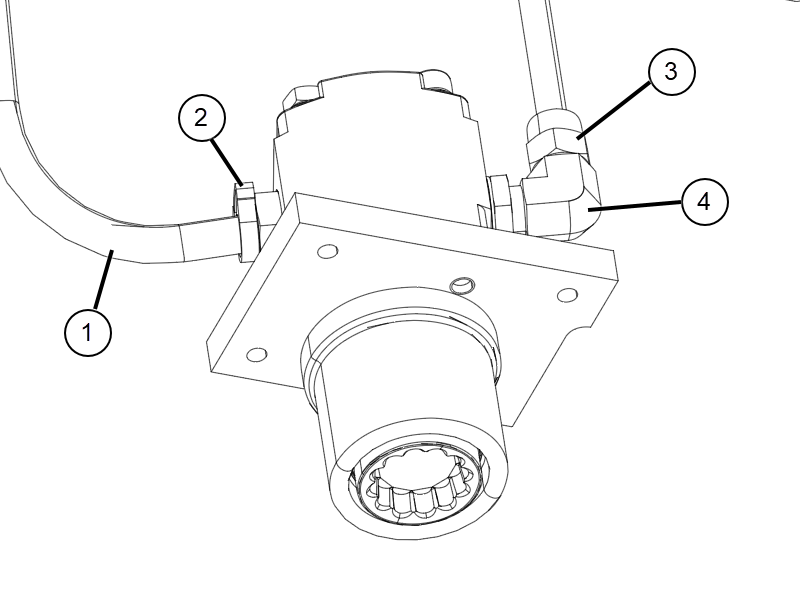
Figure 3. Table frame connector assembly rod link
1
Bracket screws
2
Rod link
3
E-clip
4
Spring
Remove the bracket screws from the frame connector assembly and remove the bracket (see Figure 3).
Detach the spring near the right rod link, and detach the matching spring near the left side rod link (see Figure 3).
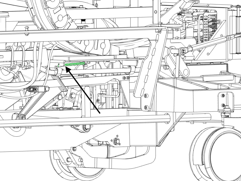
Detach the spring under the right cable track, and detach the matching spring under the left side cable track.
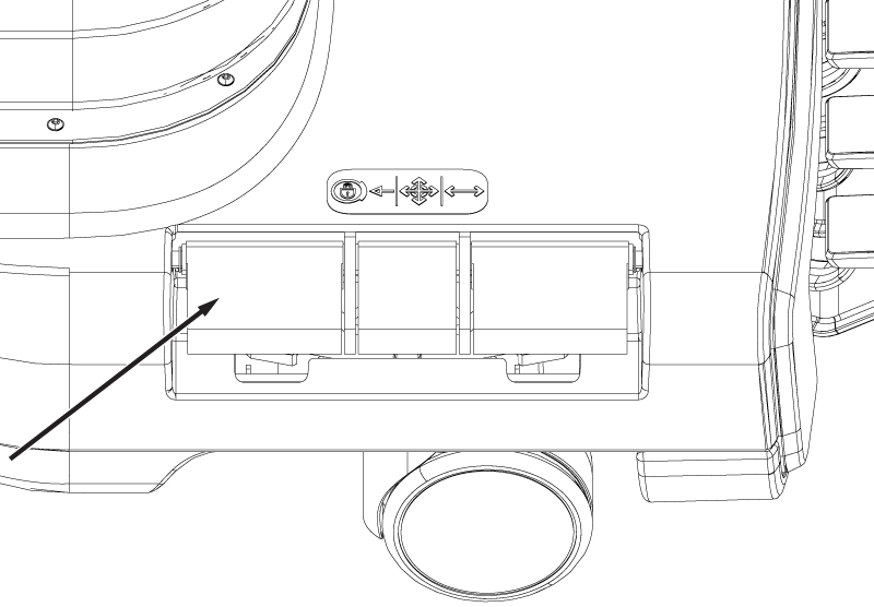
Figure 4. Cable track spring
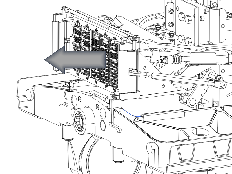
Pull the entire assembly forward to reveal the rotary pump assembly below.
Figure 5. Table frame connector assembly
Note: Before proceeding to the next step, first prepare the new hydraulic rotary pump for installation and place it within reach. Place absorbent towels underneath the work area.
On the right side of the pump, disconnect the manifold nut from the connector fitting (see Figure 7).
Note: Use a towel as plug to stop flow of fluid.
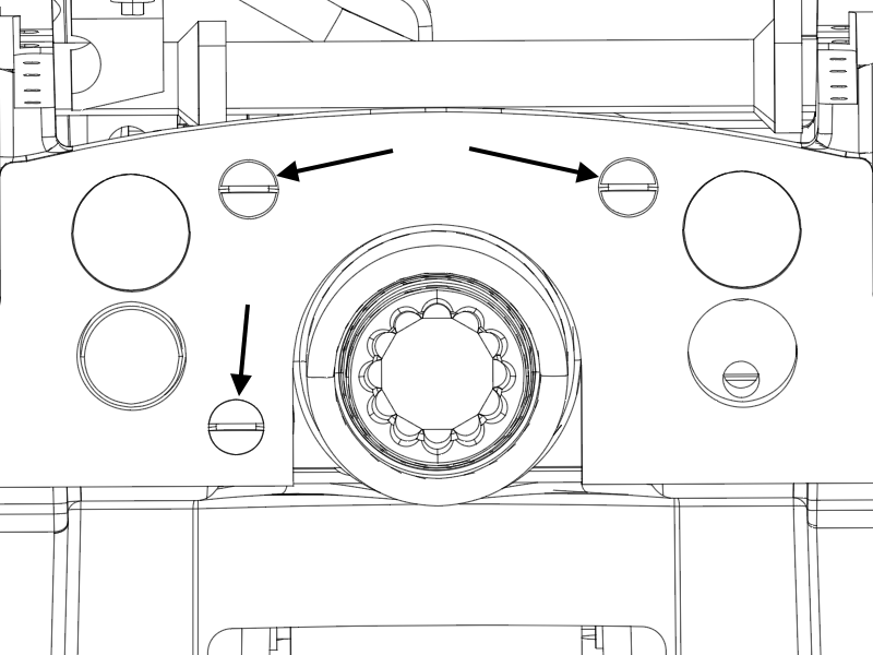
Remove three brass screws from the lower front table base. After screw removal, the pump assembly hangs freely and should allow sufficient movement. Use care in holding the rotary pump, the brass plate, and the guide coupling in place because those components (as a unit) will fall straight down.
Figure 6. Front table base screws
Lower the pump assembly. Remove the plastic clamp from the transparent low-pressure hose and then remove the hose, quickly plugging the end of the hose with a thumb or a towel to minimize leaking.

 Note: Before proceeding to the next step, first prepare the new hydraulic rotary pump for installation and place it within reach. Place absorbent towels underneath the work area.