
- SIGNA™ Hero 3.0T Service Methods
- 5852800-8EN Revision 1.0
- 00000018WIA30819230GYZ
- id_156668261.10
- Jul 13, 2021 4:27:37 PM
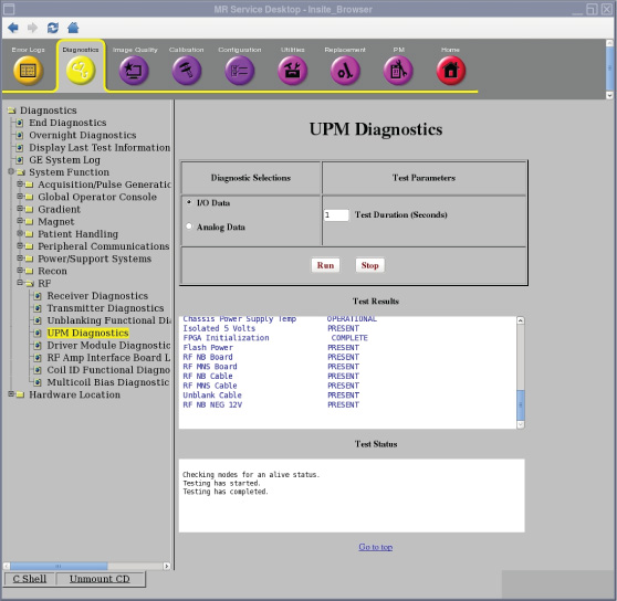
Doing the Universal Power Monitor (UPM) I/O data diagnostic
The Universal Power Monitor (UPM) I/O data diagnostic reads the power supply information from the UPM board.
Disclaimer
Depending on your service agreement, not all service tools, diagnostics, and utilities referenced in this document may be accessible. Contact your sales person for information on available service license packages.
Diagnostic description
Diagnostic path
Purpose
The UPM diagnostic reads the power supply information from the UPM board.
Components tested
- Chassis Power Supply
- Isolated 5 Volts
- FPGA Initialization
- Flash Power
- RF NB Board and Cable
- RF MNS Board and Cable
- Unblank Cable
- RF NB Negative 12 Volt
- RF MNS Negative 12 Volt
Requirements
- No special requirements.
Test sequence
- On the UPM Diagnostics screen, select I/O Data.
- Modify Test Parameters as necessary.
- Click Run.
Results
A blue color indicates a normal result. A red color indicates an error.