
- SIGNA MR355 / SIGNA MR360
- Service Manual
- 5856356-3EN Revision 5.0
- Basic Service Documentation. Copyright General Electric Company.
- 00000018WIA302EAF20GYZ
- id_131070341.4
- Apr 23, 2020 7:19:06 PM
TABLE TOP HEAD END BUMPER
Prerequisites
| Required persons | Preliminary requirements | Procedure | Finalization |
|---|---|---|---|
| 1 | 0 minutes | 120 minutes | 0 minutes |
| Item | Quantity | Effectivity | Part number | Manufacturer |
|---|---|---|---|---|
| Spanners (1/2,3/4,3/8,7/16,5/16,32) | One for each size | - | - | - |
| Circlip inserter (A-150,A170) | One for each size | - | - | - |
| Hex. Socket (9/16,3/4,3/8) | One for each size | - | - | - |
| Scale (15cms & 30 cms) | One for each size | - | - | - |
| Ball driver (5/32,5/64,3/32,1/8,7/64,9/16) | One for each size | - | - | - |
| Allen key (5/32,5/64,3/32,1/8,7/64,9/16) | One for each size | - | - | - |
| Flat nose plier | - | - | - | - |
| Cutter | - | - | - | - |
| Copper hammer | - | - | - | - |
| Screw driver (8mm, 4mm) | One for each size | - | - | - |
| Knife | - | - | - | - |
| Soft mallet | - | - | - | - |
| Torque wrench (40-120 kg-cm,10 –50 lb-ft) | - | - | - | - |
| Item | Quantity | Effectivity | Part number | Manufacturer |
|---|---|---|---|---|
| Locktite / Primer (242, 569, 680, 415, 770) | One for each size | - | - | - |
| IPA | - | - | - | - |
| White Marker | - | - | - | - |
| Grease Mobil HSC 32 | - | - | - | - |
| Cotton waste White (High grade) | - | - | - | - |
 | ||||||||
Procedure
- Remove the marked Screws of the Tabletop Panel LH and RH assembly.
Figure 2. Tabletop Panel 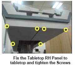
- Bent down the Panel LH and RH in order to remove the Foot end
Bumper.
Figure 3. Bent down the Panel LH and RH 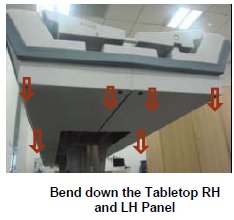
- Remove the foot end bumper from the Tabletop Panels.
Figure 4. Remove foot end bumper 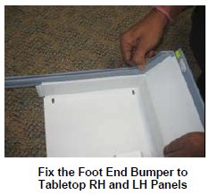
- Now take the new foot end Bumper, fix the Bumper to the Tabletop
Panels.
Figure 5. Bumper to the Tabletop Panels 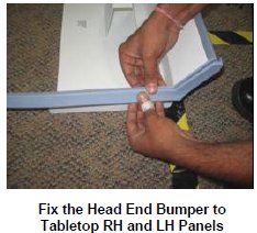
- Fix the Panel LH and RH to the tabletop, such that the Tabletop
FRP will be placed inside the Foot end bumper.
Figure 6. Fix the Panel LH and RH 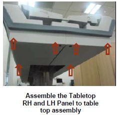
- Fix back the marked Screws of the Tabletop Panel LH and RH assembly.
Figure 7. Fix back the marked Screws 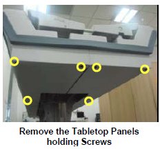
Finalization
Procedure
- Turn the System Power ON. Refer to Lockout / Tagout for System Cabinet PDU Main Breaker...
- Level the table and adjust top height. refer to LEVELING FIXED TABLE and TOP HEIGHT ADJUSTMENT.
- Fix the FRP Covers of the Table.
- Check the Table Function. Refer to TABLE CHECKS AFTER INSTALLATION .
- Perform Express Coil MCQA Test to check that the PA coil cable is properly connected.