
- SIGNA MR355 / SIGNA MR360
- Service Manual
- 5856356-3EN Revision 5.0
- Basic Service Documentation. Copyright General Electric Company.
- 00000018WIA30351030GYZ
- id_131075221.6
- Feb 4, 2021 10:13:46 PM
PA COIL COAXIAL AND DC CABLE
Prerequisites
| Required persons | Preliminary requirements | Procedure | Finalization |
|---|---|---|---|
| 1 | 0 minutes | 120 minutes | 0 minutes |
| Item | Quantity | Effectivity | Part number | Manufacturer |
|---|---|---|---|---|
| Spanners (1/2,3/4,3/8,7/16,5/16,32) | One for each size | - | - | - |
| Circlip inserter (A-150,A170) | One for each size | - | - | - |
| Hex. Socket (9/16,3/4,3/8) | One for each size | - | - | - |
| Scale (15cms & 30 cms) | One for each size | - | - | - |
| Ball driver (5/32,5/64,3/32,1/8,7/64,9/16) | One for each size | - | - | - |
| Allen key (5/32,5/64,3/32,1/8,7/64,9/16) | One for each size | - | - | - |
| Flat nose plier | - | - | - | - |
| Cutter | - | - | - | - |
| Copper hammer | - | - | - | - |
| Screw driver (8mm, 4mm) | One for each size | - | - | - |
| Knife | - | - | - | - |
| Soft mallet | - | - | - | - |
| Torque wrench (40-120 kg-cm,10 –50 lb-ft) | - | - | - | - |
| Item | Quantity | Effectivity | Part number | Manufacturer |
|---|---|---|---|---|
| Locktite / Primer (242, 569, 680, 415, 770) | One for each size | - | - | - |
| IPA | - | - | - | - |
| White Marker | - | - | - | - |
| Grease Mobil HSC 32 | - | - | - | - |
| Cotton waste White (High grade) | - | - | - | - |
| ||||||||
Procedure
- Remove PA coil from back of table and the screws set in cable
clamps.
Figure 1. Remove PA Coil and cable clamp 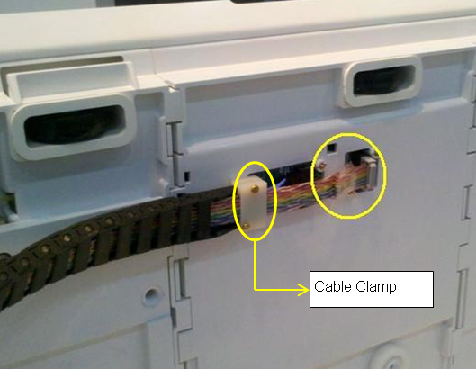
- Remove the screws underneath the cable clamp
Figure 2. Remove screws under the cable clamp 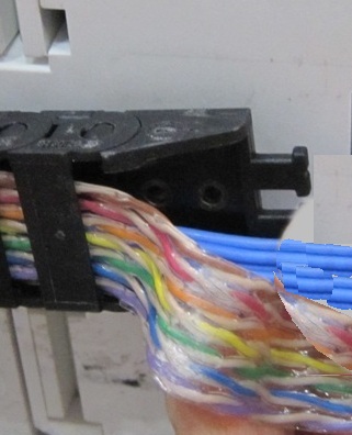
- Snap open the 3 cables clamps.Note: Install the clamp (which is in the kit of 5835711 or ordering FRU with PN: 5343302-2) if the clamps are not fixed properly as the illustration below.
Figure 3. Cable clamps 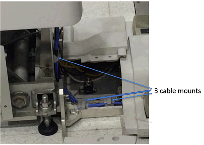
- Disconnect the Control Board Cable-2 (TEB Cable) Assembly to
the connector box.
Figure 4. Disconnect the Control Board Cable 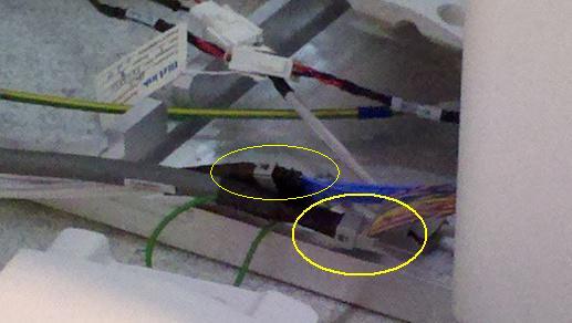
- Snap open cable track buckles.
Figure 5. Snap open cable track buckles 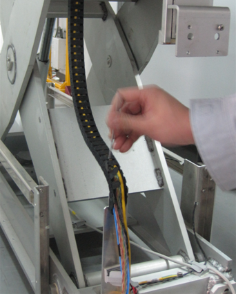
Figure 6. Open track buckles toward the direction that the tracks bulges 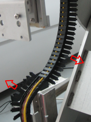
- Open the track at the end link
Figure 7. Open the track at the end link 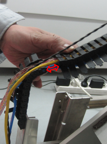
- Remove the Support Block from the table.
Figure 8. Removal of Support Block 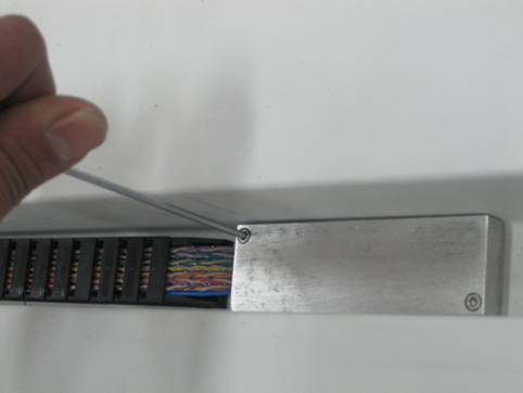
- Remove the 2 screws on the track under the cable
Figure 9. Removal of 2 screws 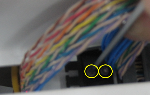
- Remove the track buckles on the other side of cable
Figure 10. Removal of cable buckles under the table 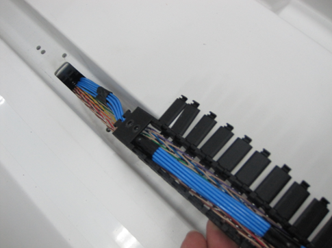
- Remove the clamp on the end of buckle, Now the control board
cable assembly is free to remove from table.
Figure 11. Remove the clamp from the buckle 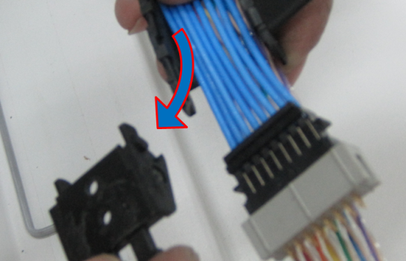
- Place the new control board cable assembly on the open cable
track to the total length.
Figure 12. Place the new control board cable 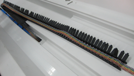
- Ensure proper projection length is given for the connection.
Figure 13. Ensure proper projection length 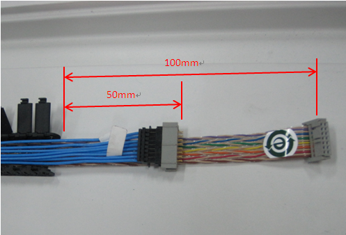 Note: Please ensure blue cable is placed on top of the colored cable.
 - Press the Cable Track keeping the cable inside the Track. See Figure 14
Figure 14. Connect the Shorter length end of the cable 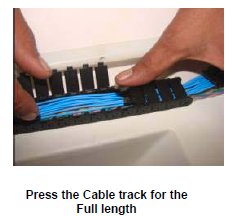
- Fix the clamp back into the cable buckle.
Figure 15. Fix the clamp back into cable buckle 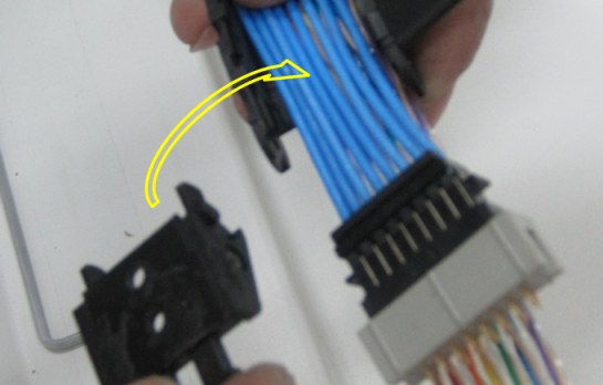
- Route the cables in the table and wind the spiral tube around
all Assemblies.
Figure 16. Route the cables 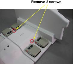
- Connect the Control Board Cable (TEB Cable) Assembly to the
connector box.
Figure 17. Control Board Cable 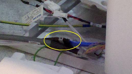
- Connect the Control Board Cable-2 (TEB Cable) Assembly to the
connector box.
Figure 18. Control Board Cable–2 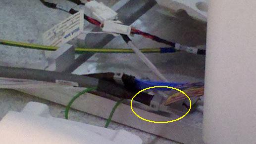
Finalization
- Turn the system Power ON. refer to Lockout / Tagout for System Cabinet PDU Main Breaker.
- Perform Express Coil MCQA Test/