
- SIGNA MR355 / SIGNA MR360
- Service Manual
- 5856356-3EN Revision 5.0
- Basic Service Documentation. Copyright General Electric Company.
- 00000018WIA300CFF20GYZ
- id_131074201.2
- Jul 5, 2019 10:25:10 PM
Dock cover Assy
Prerequisites
| Required persons | Preliminary requirements | Procedure | Finalization |
|---|---|---|---|
| 1 | 0 minutes | 120 minutes | 0 minutes |
| Item | Quantity | Effectivity | Part number | Manufacturer |
|---|---|---|---|---|
| Spanners (1/2,3/4,3/8,7/16,5/16,32) | One for each size | - | - | - |
| Circlip inserter (A-150,A170) | One for each size | - | - | - |
| Hex. Socket (9/16,3/4,3/8) | One for each size | - | - | - |
| Scale (15cms & 30 cms) | One for each size | - | - | - |
| Ball driver (5/32,5/64,3/32,1/8,7/64,9/16) | One for each size | - | - | - |
| Allen key (5/32,5/64,3/32,1/8,7/64,9/16) | One for each size | - | - | - |
| Flat nose plier | - | - | - | - |
| Cutter | - | - | - | - |
| Copper hammer | - | - | - | - |
| Screw driver (8mm, 4mm) | One for each size | - | - | - |
| Knife | - | - | - | - |
| Soft mallet | - | - | - | - |
| Torque wrench (40-120 kg-cm,10 –50 lb-ft) | - | - | - | - |
| Item | Quantity | Effectivity | Part number | Manufacturer |
|---|---|---|---|---|
| Locktite / Primer (242, 569, 680, 415, 770) | One for each size | - | - | - |
| IPA | - | - | - | - |
| White Marker | - | - | - | - |
| Grease Mobil HSC 32 | - | - | - | - |
| Cotton waste White (High grade) | - | - | - | - |
| Item | Quantity | Effectivity | Part number | Manufacturer |
|---|---|---|---|---|
| Refer to Low Height Fixed Table FRU Manual | 1 | - | - | - |
| ||||||||
Procedure
- Remove dock cover assy by 2 screws, Disconnect the Foot switch
Cable from the Control box.
Figure 1. 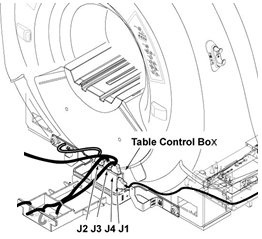
- Fix the new dock cover assy by connecting Foot switch Cable
from the Control box and installing 2 screws
Figure 2. 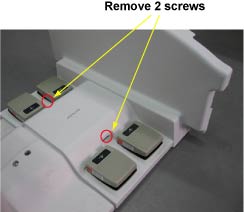
Finalization
- Turn the system power ON. Refer to Lockout / Tagout for System Cabinet PDU Main Breaker.
- Level the Table and perform Height Adjustment. Refer to LEVELING FIXED TABLE and TOP HEIGHT ADJUSTMENT.
- Fix the FRP Covers of the Table.
- Perform CRADLE HOME SENSOR CHECK .
- Check the Table Function. Refer to TABLE CHECKS AFTER INSTALLATION .
- Perform Express Coil MCQA Test to check that the PA coil cable is properly connected.