
- SIGNA MR355 / SIGNA MR360
- Service Manual
- 5856356-3EN Revision 5.0
- Basic Service Documentation. Copyright General Electric Company.
- 00000018WIA30755F20GYZ
- id_131075271.2
- Jul 5, 2019 11:18:59 PM
TOP HEIGHT ADJUSTMENT
Prerequisites
| Required persons | Preliminary requirements | Procedure | Finalization |
|---|---|---|---|
| 1 | 0 minutes | 60 minutes | 0 minutes |
| Item | Quantity | Effectivity | Part number | Manufacturer |
|---|---|---|---|---|
| Standard Tool (Non Magnetic) | 1 | - | - | - |
| ||||
About this task
For proper Patient transport Cradle movement, the Table top height should be in line with the Gantry Bridge.
Procedure
- Measure the height difference between the Guide ridge (cradle
rolling area) of Tabletop and guide ridge (cradle rolling area) of
the bridge. If adjustment is required, Remove the left top side cover
from the Table. Refer to SCISSOR COVERS.
Figure 1. Measure the height difference 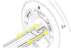
- Loosen the Lock nut of UP Limit switch (LS) actuator. Refer
to Figure 2 for the location of Up Limit Switch
Actuator.
Figure 2. Location of Up Limit Switch Actuator 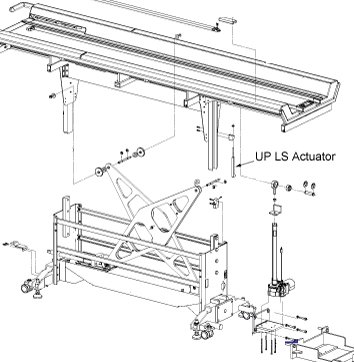
- One Clockwise rotation of the Up Limit switch actuator will
lower down the Table by 1mm. One Anti-clockwise rotation of the Up
Limit switch actuator will raise the Table by 1mm. Adjust the Up Limit
switch actuator with respect to the measured height difference. Lock
the Nut using the spanner (3/8-7/16). See Figure 3 for the adjustment. Align the position of the LS Actuator such
a way that it engages the Limit switch when table is taken to topmost
condition. Refer to Figure 4. Tighten the Lock nut
Figure 3. Up Limit Switch Actuator Adjustment 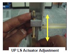
Figure 4. Allign the position of the LS Actuator 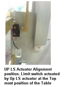
Finalization
No finalization steps.