
- SIGNA MR355 / SIGNA MR360
- Service Manual
- 5856356-3EN Revision 5.0
- Basic Service Documentation. Copyright General Electric Company.
- 00000018WIA30902030GYZ
- id_131059011.6
- Apr 23, 2020 7:22:37 PM
Table Control Box
Prerequisites
| Required persons | Preliminary requirements | Procedure | Finalization |
|---|---|---|---|
| 1 | 0 minutes | 60 minutes | 0 minutes |
| Item | Quantity | Effectivity | Part number | Manufacturer |
|---|---|---|---|---|
| Standard Tool (non-ferrous) | 1 | - | - | - |
| ||||||||||||
About this task
Note:
If Table Control Box 5458804 installed in site need to be replaced, please order 5458804/5458804-2 for replacement.
If Table Control Box 5458804-2 installed in site need to be replaced, please order 5458804-2 for replacement.
Procedure
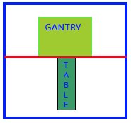
- Remove FRP bottom covers of Fixed Table.
- Remove the Rubber cap and then screws of the FRP bottom cover
on the near the Gantry end of the Table.
Figure 2. FRP Cover1 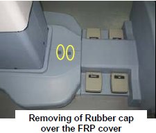
- Similarly remove the cap and screws of the FRP bottom cover
on the rear end of the Table.
Figure 3. FRP Cover2 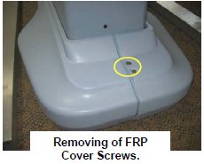
- Remove the right Bottom FRP Cover. Similarly remove the left
Bottom FRP cover on the other side
Figure 4. FRP Cover3 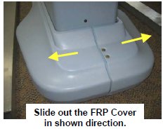
- Now remove the Dock FRP Cover Locking screws and then the Dock
FRP cover carefully.
Figure 5. FRP Cover4 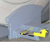
- Remove the Rubber cap and then screws of the FRP bottom cover
on the near the Gantry end of the Table.
- Disconnect cables from Table Control Box.
Figure 6. Cables of Table Control Box 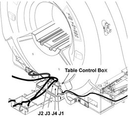
- Remove defective Table Control Box by removing one screw.
Figure 7. Convert Board 3 Removal 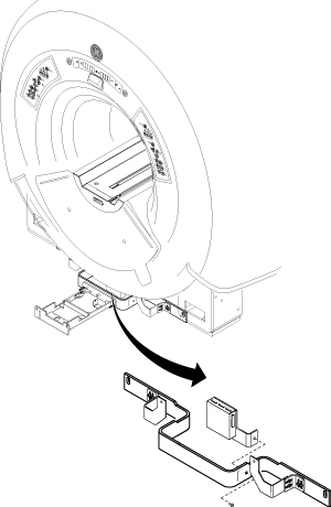
Finalization
No finalization steps.