• SIGNA MR355 / SIGNA MR360
  • Service Manual
  • 5856356-3EN Revision 5.0
  • Basic Service Documentation. Copyright General Electric Company.
  • Object ID: 00000018WIA303E1030GYZ
  • Topic ID: id_13106916 Version: 1.7
  • Date: Jul 5, 2019 10:46:04 PM

Slice Thickness and Resolution

Prerequisites

Table 1. Personnel requirements
Required personsPreliminary requirementsProcedureFinalization
1Not Applicable30 minutesNot Applicable
Table 2. Tools and test equipment
ItemQuantityEffectivityPart numberManufacturer
Axial Slice Analysis Phantom1-

46-287379G1

-
Coronal/Sagittal Slice Analysis Phantom1-

46 258559G1

-
Phantom Positioner Assembly1-

46 258709G1

-
Table 3. Safety
Note:

Equipment damage possibility. Completely remove the quad head coil from the cradle before performing any body scans. Failure to do so may damage the head coil T/R network.

Table 4. Required conditions
ConditionReferenceEffectivity

--

About this task

Slice thickness and spatial resolution tests check the dimensional characteristics of the scanner. As this is related to the gradients being used, for the TwinSpeed the tests should be repeated for each gradient separately. In This document you will find:

HEAD SCANS

Procedure

  1. Place the Axial Slice Analysis Phantom in the head coil. Position the filler plugs (resolution end of the phantom) toward the foot-end of the table. Landmark the phantom on the center line (see Illustration 1-2).
    Figure 1. Landmarking Phantom In Split Head Coil
  2. At the keypad on the front magnet enclosure, press LANDMARK and MOVE TO SCAN.
  3. At the operator workspace, select the Scan icon in the desktop control panel, if you have not already done so.
  4. Click on [Autoview], just below the Autoview image display screen. Your images will be displayed automatically.
  5. Prepare the Head Slice Thickness scan, Series #1 per the scan protocol.
  6. Click on Auto Prescan. When the prescan is complete, record R1, R2, TG, and system frequency values on Data Sheet. Reduce TG by 10 counts, then click on Scan.
    Note:

    The autoprescan TG needs to be reduced by 10 counts for the Spin Echo scans, but not for the Gradient Echo scans.

  7. After scan #1 is complete, click on [New Series]. Prepare for scan #2, Head Slice Thickness Series 2.
  8. Click on [Auto Prescan]. When the prescan is complete, record R1, R2, TG, and system frequency values on Data Sheet. Reduce TG by 10 counts, then click on [Scan]. After scan #2 is complete, click on [New Series].
  9. After scan #2 is complete, click on [New Series]. Prepare for scan #3, Head Slice Thickness Series 3.
  10. Click on [Auto Prescan]. When the prescan is complete, record R1, R2, TG, and system frequency values on Data Sheet 1. Reduce TG by 10 counts, then click on [Scan].
  11. After scan #3 is complete, click on [New Series]. Prepare for scan #4, Head Slice Thickness Series 5,
  12. After scan #4 is complete, click on [New Series]. Prepare for scan #5, Head Slice Thickness (3D, Localizer),
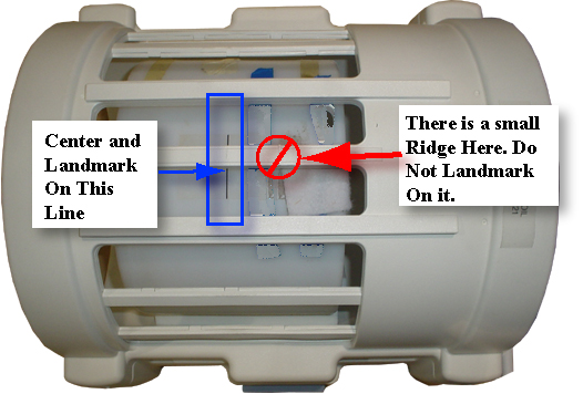
  13. Click on [Scan] (system will Auto Prescan first). Record R1, R2, TG, and system frequency values on Data Sheet 1.
    Note:

    Remember to position cursor in center of localizer image for prescribing the 3D volume scan. See Figure 2.

    Figure 2. CURSOR PLACEMENT FOR PRESCRIBING SLICE THICKNESS 3D SCAN
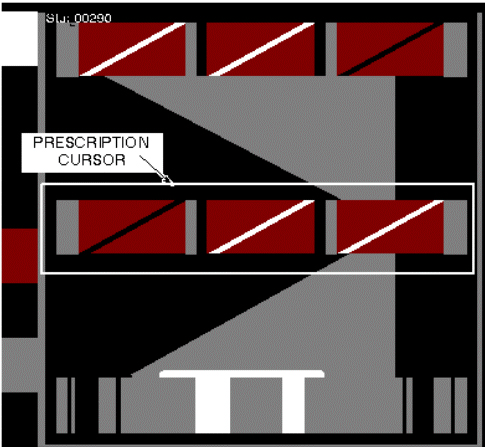
  14. After scan #5 is complete, click on [New Series]. Prepare for scan #6, Head Slice Thickness #6.
  15. For analysis, refer to section 3- Slice Thickness Image Analysis and section 4- Resolution Image Analysis. Record all data on Data Sheet. For TwinSpeed, identify the GradMode used.
    Note:

    When you perform the analysis on the 3D volume scan, use the image nearest to isocenter.

Body Scan Procedure

Procedure

  1. Remove the head coil from the cradle.
  2. Place the Sagittal/Coronal Slice Analysis Phantom and phantom holder on the cradle, approximately halfway along the length of the cradle. Position with the resolution block on the right side of phantom (when facing the magnet) and slice thickness block on the left side. See Figure 31. Landmark phantom on line along the longitudinal axis and the middle line around the circumference. Press MOVE TO SCAN.
    Figure 3. Coronal/Sagittal Slice Analysis Phantom Positioning
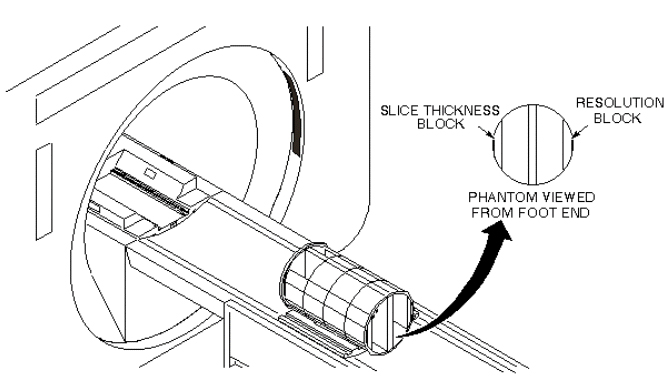
    Note:

    Important! On all scans, the phantom must be positioned at isocenter to prevent image wrap.

  3. At operator workspace, select the Scan icon in the desktop control panel, if you have not already done so.
  4. Click on Autoview, just below the Autoview image display screen. Your images will be displayed automatically.
  5. Prepare Body Slice Thickness scan.
  6. Click on Auto Prescan. When the prescan is complete, record R1, R2, TG, and system frequency values on Data Sheet. Reduce TG by 10 counts, then click on Scan.
  7. After scan #1 completes, click on New Series and set up scan #2, Body Slice Thickness Series 2
  8. Click on Auto Prescan. When the prescan is complete, record R1, R2, TG, and system frequency values on Data Sheet. Reduce TG by 10 counts, then click on Scan.
  9. After scan #2 completes, click on New Series and set up scan #3, Body Slice Thickness Series 3
  10. Click on Auto Prescan. When the prescan is complete, record R1, R2, TG, and system frequency values on Data Sheet. Reduce TG by 10 counts, then click on Scan.
  11. After scan #3 completes, click on New Series and set up scan #4, Body Slice Thickness Series 4
  12. Click on Auto Prescan. Reduce TG by 10 counts, then click on Scan.
  13. After the localizer scan #4 is complete, click on New Series and set up Body Slice Thickness Series 5.
  14. Click on Auto Prescan. When prescan is complete, record R1, R2, TG, and system frequency values on Data Sheet. Reduce TG by 10 counts, then click on Scan.
  15. After scan #5 is complete, click on New Series and set up scan #6, Body Slice Thickness Series 6.
  16. Click on Auto Prescan. When prescan is complete, record R1, R2, TG, and system frequency values on Data Sheet. Reduce TG by 10 counts, then click on [Scan].
  17. After scan #6 is complete, click on [New Series] and set up scan #7, Body Slice Thickness Series 7.
  18. Click on Auto Prescan. When prescan is complete, record R1, R2, TG, and system frequency values on Data Sheet. Reduce TG by 10 counts, then click on [Scan].
  19. For analysis, see SLICE THICKNESS IMAGE ANALYSIS Slice Thickness Image Analysis. Record all body data in Data Sheet. For TwinSpeed, identify the GradMode used.

SLICE THICKNESS IMAGE ANALYSIS

Procedure

  1. Select Image Quality, under Utility on the Service Desktop, see Figure 4
    Figure 4. STARTING THE IMAGE QUALITY TOOL FROM THE SERVICE BROWSER
  2. For TwinSpeed, highlight the same GradMode as was used with the slice thickness scans, then click on [OK]
  3. A NEMA Image Quality window will appear on the desktop. Type 3(Slice Thickness/ Resolution Check) and press Enter for. See Table 5.
    Table 5. NEMA IMAGE QUALITY MENU


                                <<< Nema Image Quality Analysis>>>
       1. Signal to Noise Check
       2. Slice Offset Checks
       3. Slice Thickness/resolution Check
       4. T2 Uniformity Check
       5. Full Field Distortion Check
       6. Exit NEMA Test

    Select Test:  3 <Enter>
                              

  4. Select the exam, series, and image numbers for the image to be analyzed.
  5. Analysis then begins. The final values are displayed on the screen (see Table 61).
    Table 6. SLICE THICKNESS REPORT


                                Head Axial Slick Thickness
    Scan Location (mm)   :   XXX.XXX
    Nominal Thickness    :     X.XXX
    Measured Thickness   :     X.XXX


  6. Record the Scan Location, Nominal Thickness, and Measured Thickness in Data Sheet 1 for Head, and Data Data Sheet for Body. For TwinSpeed, identify the GradMode used.
  7. Repeat steps Step 3 through 6 above for analysis of the remaining images.
  8. Store all completed data sheets on floppy disk for future reference.

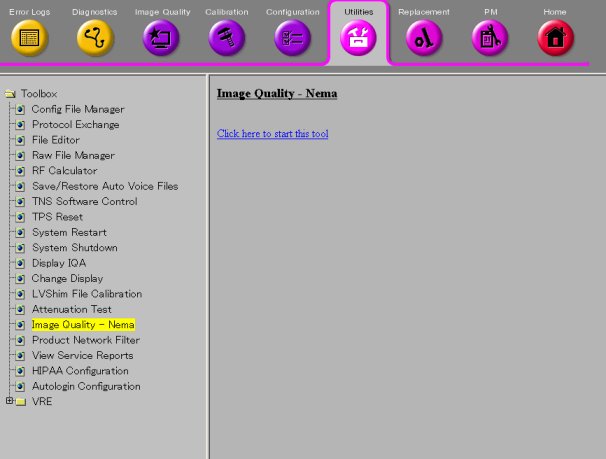
RESOLUTION IMAGE ANALYSIS

About this task

This test measures the smallest resolvable line groups in a high-contrast resolution phantom. The phantom line pair groups are oriented at a 45° angle (reference to the horizontal plane) in order to measure system resolution in the frequency and phase axes. Resolution images are acquired during the slice thickness scans, so additional scans are not required for this test.

Procedure

  1. Perform the head resolution check as follows:
    1. Using Image Browser, select the head slice thick exam.
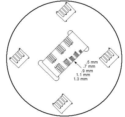
    2. Display the 10-mm, I80 image (which should be Series 3, image 1 for head; image 3 for body exam), using [Viewer]. See Illustration 4-1.
      Figure 5. Resolution Test Image
    3. Select single image icon under [Format] and adjust the Zoom function to obtain an 8.0 magnification. The image can then be panned to better view the resolution block, by holding down the right mouse button while positioning the image.
    4. After the magnified image is positioned, set the window width to 1 and vary the window level to give the best visible separation between the lines and spaces in the line group being analyzed.
    5. Record level setting and smallest resolvable line pair group in Data Sheet 3, Resolution Data. For TwinSpeed, identify the GradMode used.
  2. Repeat Step 1 to perform body resolution check. Use the Body Slice Thick exam, and display the 10-mm, L80 image (should be Series 3, Image 3).

Finalization

No finalization steps.