
- SIGNA MR355 / SIGNA MR360
- Service Manual
- 5856356-3EN Revision 5.0
- Basic Service Documentation. Copyright General Electric Company.
- 00000018WIA30E18F20GYZ
- id_131075253.0
- Feb 21, 2021 9:11:12 PM
Forward Reverse Quadrature Check
Prerequisites
| Required persons | Preliminary requirements | Procedure | Finalization |
|---|---|---|---|
| 1 | Not Applicable | 30 minutes minutes | Not Applicable |
| Item | Quantity | Effectivity | Part number | Manufacturer |
|---|---|---|---|---|
| 1.5T Body Loader and Phantom | 1 | 1.5T |
2371511 | - |
Note:
Equipment damage possibility. Completely remove the Quad Head Coil from the cradle before performing any body scans. Failure to do so may damage head coil T/R network. | ||||
About this task
This section determines the quadrature balance of the quad coil and the phase splitter network. In this test, the Body or Head TLT Sphere phantom is scanned with the quadrature coil connected in two ways. First, an image is taken with the quadrature coil as presently connected. Next, the cables to the quadrature switches are reversed, and the phantom is scanned a second time using the same protocol. The resultant images are analyzed to verify proper quadrature drive function and cable configuration. This procedure consist of the following:
-
Body Forward/Reverse Quadrature Scans.
-
Forward/Reverse Quadrature Test Image Analysis.
Body Forward/Reverse Quadrature Scans
Procedure
- Reverse the black I and Q cables connecting to J1 and J2 at the bulkhead.
Figure 2. J1 and J2 at bulkhead 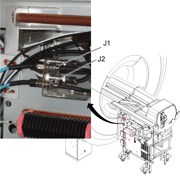
Forward/Reverse Quadrative Test Image Analysis
About this task
This analysis procedure applies only to body scans.
Procedure
- Use a square Region of Interest (ROI) of 4000 mm2 ± 50 mm2, located
at the center of the image. Measure the mean pixel value (MPV1). In
the viewer, this is shown as m=xxx. Jot down this value. See Figure 3.
MPV1: ______________ MPV2: ______________ Figure 3. Image Comparison 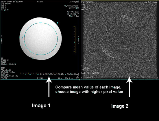
Finalization
Procedure
- Restore the system to patient scanning condition.
- Do a test scan to ensure the system is running properly.