
- SIGNA MR355 / SIGNA MR360
- Service Manual
- 5856356-3EN Revision 5.0
- Basic Service Documentation. Copyright General Electric Company.
- 00000018WIA30206F20GYZ
- id_131057891.3
- Jul 5, 2019 10:25:10 PM
PAC Leakage Current Test
Prerequisites
| Required persons | Preliminary requirements | Procedure | Finalization |
|---|---|---|---|
| 1 | Not Applicable | 10 minutes | Not Applicable |
| Item | Quantity | Effectivity | Part number | Manufacturer |
|---|---|---|---|---|
| Dale 600/601 (120VAC) Safety Analyzer | 1 | - |
46-328406G1 | - |
| Dale 600E/601E (220VAC) Safety Analyzer | 1 | - |
46-328406G2 | - |
| Fluke ESA612 Electrical Safety Analyzer | 1 | - |
5453348 | - |
| ||||||||||||
About this task
When Safety Analyzer Kits are sent in for calibration, the units are being upgraded with the Dale 601/601E Safety Analyzer (generally Americas and Asia) or the Fluke ESA612 Safety Analyzer (generally Europe).
This procedure is divided into three sections: first the Dale 600/600E; next the Dale 601/601E; and finally the Fluke ESA612.
Data Sheet for Recording Leakage Current Data
About this task
Use the supplied data sheet to record the leakage current data. Table 4 is a reference of what is contained on the data sheet. Print the form. 2087498.pdf
| LEAD SELECT POSITION | METER READING NORMAL POSITION (microamps) | METER READING REVERSE POSITION (microamps) |
|---|---|---|
| Patient (Lead to Ground) Leakage Current | ||
| Right Leg (RL) | ||
| Right Arm (RA) | ||
| Left Arm (LA) | ||
| Left Leg (LL) | ||
| Patient (Lead to Lead) Auxiliary Current | ||
| RL | ||
| RA | ||
| LA | ||
| LL | ||
| M.A.P. (Isolation Tests) | ||
| ALL LEADS M.A.P. Test | ||
Using Dale 600/600E Safety Analyzer
Procedure
DANGER 
Plug the Analyzer into a power source in the magnet room, which allows access to the PAC Remote Interface Assembly while staying at least 20 inches (51 cm) from the magnet.Notice Figure 1. Location Of The PAC Remote Interface ASM For LCC/CX/K4 Magnet 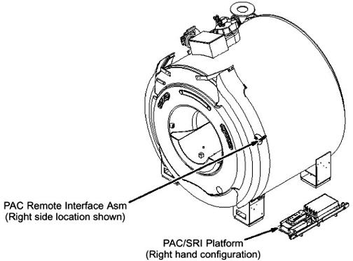
- At Physiological Acquisition Controller (PAC) Remote Interface
Assembly, connect the Patient Lead cable and the Cardiac Lead Set
at the ECG connector.
The ECG connector is round and is labeled with “ECG” or a heart symbol.
Figure 2. ECG Connector (Example) 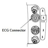
- Connect cardiac leads to Dale 600/600E (46-328406G1). See Figure 3.
Figure 3. Dale 600 Analyzer 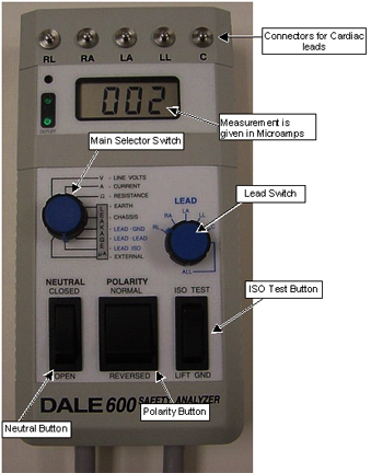
Using Dale 601/601E Safety Analyzer
Procedure
DANGER
Plug the Analyzer into a power source in the magnet room, which allows access to the PAC Remote Interface Assembly while staying at least 20 inches (51 cm) from the magnet.Notice Figure 4. Location Of The PAC Remote Interface ASM For LCC/CX/K4 Magnet - At Physiological Acquisition Controller (PAC) Remote Interface
Assembly, connect the Patient Lead cable and the Cardiac Lead Set
at the ECG connector.
The ECG connector is round and is labeled with “ECG” or a heart symbol.
Figure 5. ECG Connector (Example) - Verify that the Test Load selector switch is set at 601 for
IEC601.1. See Figure 6.
Figure 6. Test Load Selector Switch Setting 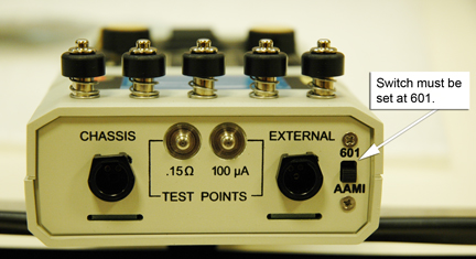
- Connect the ECG leads to Dale 601/601E. See Figure 7. Not all systems
will have the Cardiac (C) lead.
Figure 7. Dale 601/601E Analyzer: Connecting Leads 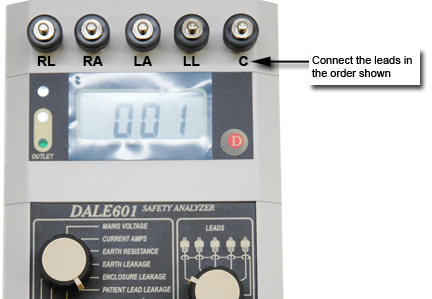
- Place the L2 (Neutral) Switch in the CLOSED position. See Figure 8.
Figure 8. Dale 601/601E Safety Analyzer 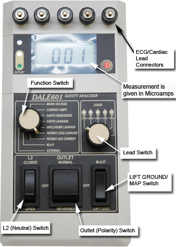 Note:
Note:Be sure to pause in the OFF (Middle) position when switching polarity from normal to reverse
Using Fluke ESA612 Safety Analyzer
Setting up Fluke ESA612 Safety Analyzer
Procedure
DANGER
Plug the Analyzer into a power source in the magnet room, which allows access to the PAC Remote Interface Assembly while staying at least 20 inches (51 cm) from the magnet.Notice Figure 9. Location Of The PAC Remote Interface ASM For LCC/CX/K4 Magnet - At Physiological Acquisition Controller (PAC) Remote Interface
Assembly, connect the Patient Lead cable and the Cardiac Lead Set
at the ECG connector. .
The ECG connector is round and is labeled with “ECG” or a heart symbol.
Figure 10. ECG Connector (Example) - Connect the ECG leads to the Fluke BJ2ECG Input Jack Adapter,
matching:
-
Right Arm (RA) lead to RA Input Jack Adapter
-
Left Leg (LL) lead to LL Input Jack Adapter
-
Left Arm (LA) lead to LA Input Jack Adapter
-
Right Leg (RL) lead to RL Input Jack Adapter
The fifth Input Jack Adapter, Cardiac (C), is not used for these tests.
Figure 11. Fluke ESA612 Safety Analyzer 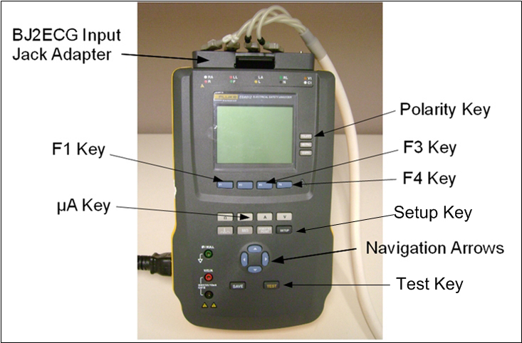
-
Testing Lead to Lead with the Fluke ESA612 Safety Analyzer
About this task
Detail of [F1] ~ [F4] Key selection will be shown on the display.
Procedure
Testing Lead to Ground with the Fluke ESA612 Safety Analyzer
Procedure
Finalization
Procedure
DANGER
Disconnect the Cardiac Lead Set from Safety Analyzer.Notice - Remove the Patient Lead cable from the ECG Connector.
- Unplug the Safety Analyzer.