
- SIGNA MR355 / SIGNA MR360
- Service Manual
- 5856356-3EN Revision 5.0
- Basic Service Documentation. Copyright General Electric Company.
- 00000018WIA30DD1030GYZ
- id_131067741.1
- Jul 6, 2019 12:17:32 AM
Slice Offset Checks
Prerequisites
| Required persons | Preliminary requirements | Procedure | Finalization |
|---|---|---|---|
| 1 | Not Applicable | 30 minutes | Not Applicable |
| Item | Quantity | Effectivity | Part number | Manufacturer |
|---|---|---|---|---|
| Head Axial Slice Analysis Phantom | 1 | - |
46-287379G1 | - |
About this task
Slice offset is determined by performing a multiscan sequence on the Head Axial Slice Analysis Phantom, and imaging between the slice thickness plates. There are two ramps inside the phantom that extend between the three plates. The ramps originate at the center of the center plate and rise at an angle of 63.4°. The offset between the image slices is calculated by measuring the length of the ramp image.
Note:
It is important that the correct Head Axial Slice Analysis Phantom, 46-287379G1, is used in this procedure. Other Head Axial Slice Analysis Phantoms will not give the correct results.
2D SCANS
Procedure
- Place the Axial Slice Analysis Phantom in the head coil. Position
the filler plugs (resolution end of the phantom) toward the foot-end
of the table. Landmark the phantom on the center line.
Figure 1. AXIAL SLICE ANALYSIS PHANTOM POSITIONING 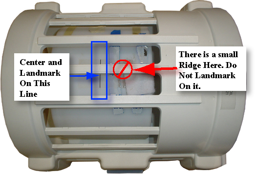
3D SCANS
Procedure
- A slab box cursor appears on the image. Position the cursor
over the center bar of the image (see Figure 2),
then click on Accept, Save Series. Then Prepare to Scan.
Figure 2. CURSOR PLACEMENT FOR PRESCRIBING SLICE OFFSET 3D SCAN 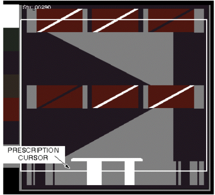
SLICE OFFSET IMAGE ANALYSIS
Procedure
- To run the Image Quality Analysis – NEMA tool from the Service
Desktop, follow the instructions on Figure 3,
below.
Figure 3. STARTING THE IMAGE QUALITY - NEMA TOOL FROM THE SERVICE BROWSER 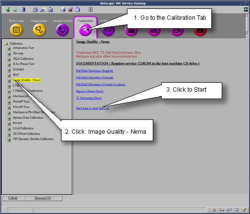
- A NEMA Image Quality window appears on the desktop. Type 2Enter for Slice Offset Checks.
See Figure 4.
Figure 4. NEMA IMAGE QUALITY MENU 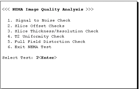
- Analysis then begins. The final values are displayed on the
screen, as shown in Figure 5.
Figure 5. SLICE OFFSET RESULTS SCREEN 
Finalization
Procedure
- Return the system to a patient scanning condition.
- Do a check scan to insure proper operation.