Basic Service Documentation. Copyright General Electric Company.
Object ID: 00000018WIA30E81030GYZ
Topic ID: id_13106492 Version: 1.1
Date: Jul 6, 2019 12:17:31 AM
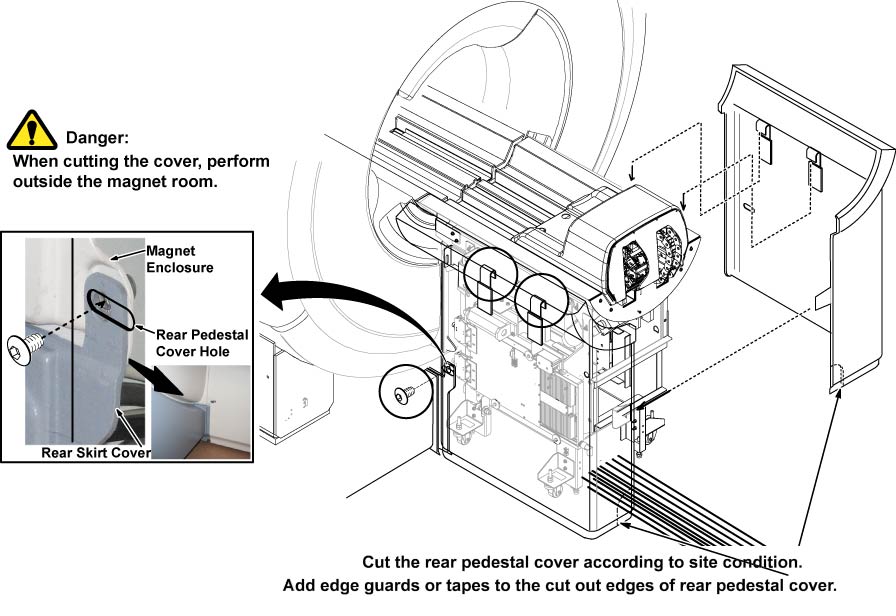
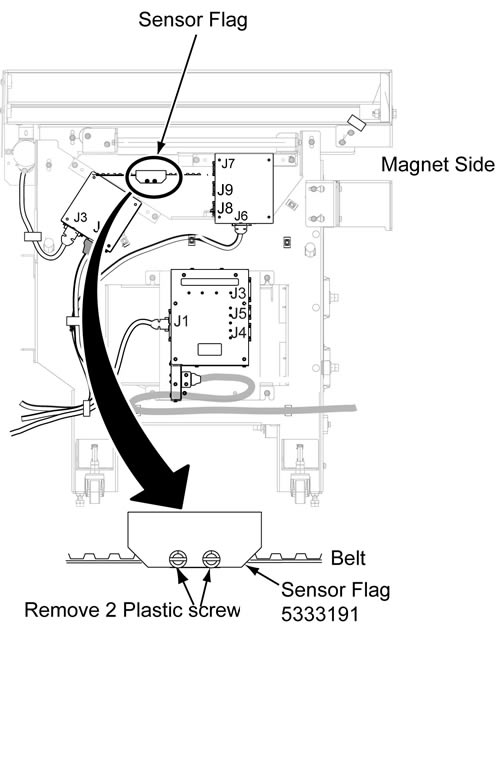
Rear Pedestal Sensor Flag Replacement
Prerequisites
Table 1. Personnel requirements
Required persons
Preliminary requirements
Procedure
Finalization
1
Not Applicable
30 minutes
Not Applicable
Table 2. Tools and test equipment
Item
Quantity
Effectivity
Part number
Manufacturer
Non Magnetic Tool
Set
1
-
-
-
Table 3. Safety
Warning
FERROUS MATERIAL HAZARD!!
THE PULLEY ASSEMBLY CONTAINS PARTS MADE WITH FERROUS COMPONENTS.
HOLDING THIS ASSEMBLY TOO CLOSE TO THE MAGNET BORE WILL FORCIBLY ATTRACT
IT TO THE MAGNET.
TO PREVENT POSSIBLE BODILY INJURY, OR DAMAGE TO COMPONENTS,
REMOVE THE ASSEMBLY DIRECTLY, NOT MOVING IT IN THE MAGNETIC FIELD
MORE THAN IS NECESSARY.
Warning
FERROUS MATERIAL HAZARD!!
THE FRONT BRIDGE SUPPORT ASSEMBLY CONTAINS PARTS MADE WITH
FERROUS COMPONENTS. HOLDING THIS ASSEMBLY TOO CLOSE TO THE MAGNET
BORE WILL FORCIBLY ATTRACT IT TO THE MAGNET.
TO PREVENT POSSIBLE BODILY INJURY, OR DAMAGE TO COMPONENTS,
REMOVE THE ASSEMBLY DIRECTLY, NOT MOVING IT IN THE MAGNETIC FIELD
MORE THAN IS NECESSARY.
Restore it by reversing the order of the removal procedure.
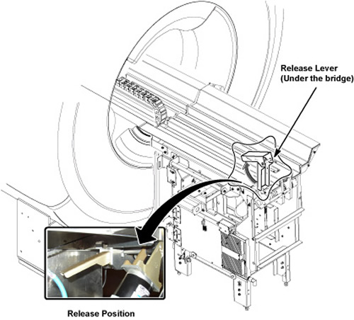
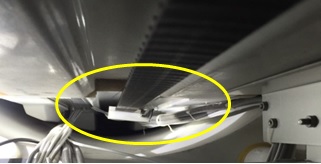
To ensure the cables under bridge have been tightened by ribbons.
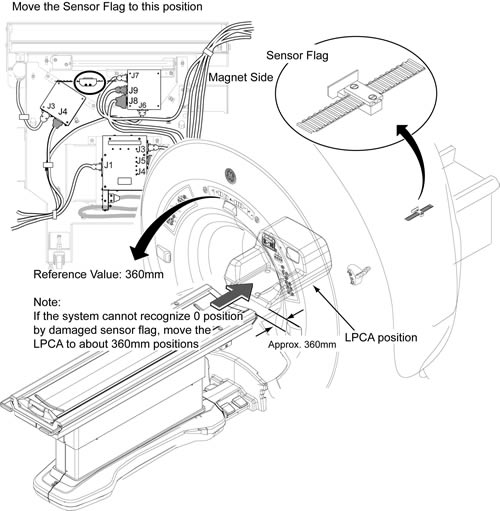
Move table advance to reach home position, and double check
there is no contact between cables (under bridge) and home sensor
flag when cradle belt is moving.