When servicing any magnetic equipment, it is critically important that the service engineer consciously plan the path to be taken when moving highly ferrous devices in the magnet environment. The magnetic field in this path must not exceed 200 Gauss and the path should be as far from the magnet as practical.
Safety Requirements
The static magnetic field in any portion of the service path must not exceed 200 Gauss.
Two (2) MR safety trained personnel must be present at all times when servicing highly ferrous devices in the areas of magnetic fields.
When planning a service path, it is critical that the path be clear and sufficiently wide. Ensure that there are no trip hazards, obstacles, clutter, slippery surfaces or other items even partially restricting the path. If there are portable obstacles in a path, remove them from the area and replace them after the service action is completed. It is required to walk the path prior to beginning service to ensure that there is sufficient space through which to pass for yourself and the object being serviced.
Warning
ELECTROCUTION HAZARD!
DANGEROUS VOLTAGES ARE PRESENT AROUND THE MAGNET SUBSYSTEM
WHEN ENERGIZED.
LOCK AND TAG OUT POWER TO THE MAGNET ROOM BEFORE STARTING
WORK.
CAUTION
FERROUS MATERIAL HAZARD!!
LONGITUDINAL DRIVE MOTOR CONTAINS FERROUS MATERIAL.
HOLDING THIS ASSEMBLY TOO CLOSE TO THE MAGNET BORE WILL
FORCIBLY ATTRACT IT TO THE MAGNET. TO PREVENT POSSIBLE BODILY INJURY
OR MATERIAL DAMAGE, REMOVE LONGITUDINAL DRIVE MOTOR AND MOUNTING BRACKET
FROM MAGNET ROOM TO INSTALL NEW LONGITUDINAL DRIVE MOTOR (See #id_13107295__SL3567448-1149649 for proper
process to remove motor from Magnet Room). TWO PEOPLE ARE REQUIRED
AT ALL TIMES FOR THIS PROCEDURE.
The Longitudinal Drive is located in the rear pedestal. Two
people are required to replace the Longitudinal Drive Motor due to
the its strong attraction to the magnet.
Procedure
Remove all covers from Rear Pedestal. Refer to Cover Removal
Remove cover of Bridge end.
Remove the LPCA cover.
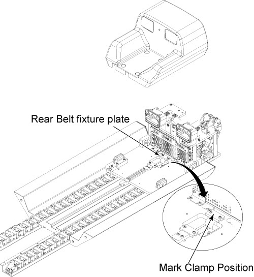
Mark on the belt at the edge of fixture plate with white pen
so that the belt tension can be restored it is after the replacement.
Release Drive Belt tension by flipping lever under Rear Pedestal.
Remove rear belt fixture plates through removing 2 screws.
Figure 1. Remove Rear Belt Fixture Plate
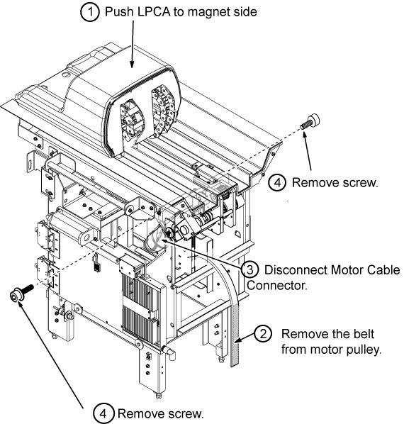
Remove the LPCA from the Rear pedestal, push the LPCA to magnet
side.
Remove the Belt from Motor Assy.
Disconnect motor cable connectors.
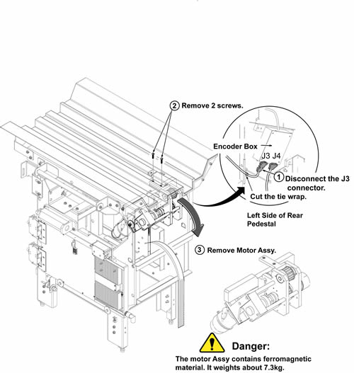
Remove 2 cap screws from both side of rear pedestal.
Figure 2. Fixing Screw of Drive Motor Assy
Cut the tie wrap and disconnect J3 of encoder connector from
Encoder Box.
CAUTION
FERROUS MATERIAL HAZARD !!
LONGITUDINAL DRIVE MOTOR CONTAINS FERROUS MATERIAL.
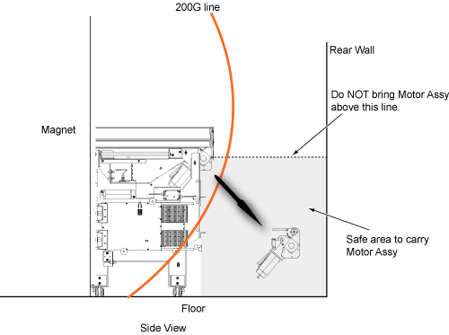
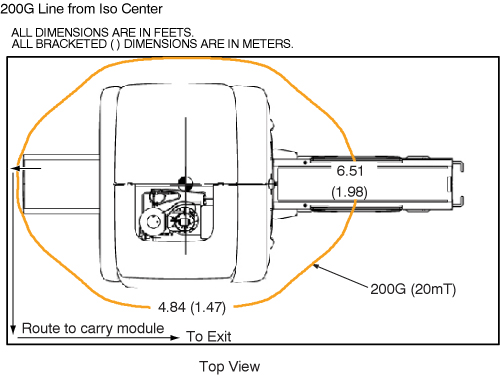
HOLDING THIS ASSEMBLY TOO CLOSE TO THE MAGNET BORE WILL FORCIBLY ATTRACT IT TO THE MAGNET. TO PREVENT POSSIBLE BODILY INJURY OR MATERIAL DAMAGE, REMOVE LONGITUDINAL DRIVE MOTOR ASSY TOWARD THE REAR WALL BELOW THE ORIGINAL MOTOR ASSY LEVEL AS #id_13107295__SL3567448-1149649 AT REAR OF THE MAGNET. CARRY THE ASSY OUTSIDE OF 200G LINE ALONG THE WALL TO THE EXIT AS #id_13107295__SL3567449-1149649.REMOVAL AT REAR OF THE MAGNET200G LINE AND ROUTE TO CARRY MODULE
CAUTION
POSSIBLE PERSONAL INJURY!
DO NOT PLACE ANY PART OF THE HUMAN BODY IN THE PATH BETWEEN
THE MOTOR ASSY AND THE MAGNET.
Hold the Motor Assy below the bridge and remove the 2 screws
on the bridge.
Carefully slide motor assy to the rear direction and remove
it toward the rear wall below the original motor assy level.
Figure 3. Remove Motor Assy
With two people holding the motor assembly, exit the magnet
room by walking as close to the wall on the coldhead side of the magnet
as possible.