| DANGER |
|---|
 | STRONG MAGNETIC FIELD! FERROUS MATERIALS CAN BECOME DANGEROUS PROJECTILES IN THE
PRESENCE OF THE MAGNETIC FIELD PRODUCED BY THE SIGNA MAGNET. Do not Bring any ferromagnetic tools or equipment into
the magnet room. |
| Warning |
|---|
| ELECTROCUTION HAZARD! DANGEROUS VOLTAGES ARE PRESENT AROUND THE MAGNET SUBSYSTEM
WHEN ENERGIZED. LOCK AND TAG OUT POWER TO THE magnet room BEFORE STARTING
WORK. |
| Warning |
|---|
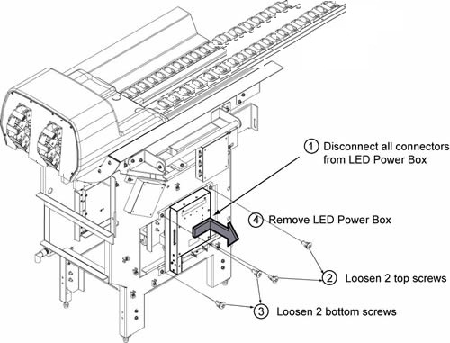
| STRONG MAGNETIC FIELD! FERROUS MATERIAL INSIDE OF LED POWER BOX PLEASE REPLACE IT CAREFULLY |
|