Basic Service Documentation. Copyright General Electric Company.
Object ID: 00000018WIA30F01030GYZ
Topic ID: id_13106458 Version: 1.3
Date: Jul 6, 2019 12:17:31 AM
Longitudinal Drive Motor and Gear Box Replacement
Prerequisites
Table 1. Personnel requirements
Required persons
Preliminary requirements
Procedure
Finalization
2
Not Applicable
30 minutes
Not Applicable
Table 2. Tools and test equipment
Item
Quantity
Effectivity
Part number
Manufacturer
Non-magnetic Tool
Set (Including flat-head screw driver)
1
-
-
-
PPE (Including gloves)
-
-
-
-
Table 3. Replacement parts
Item
Quantity
Effectivity
Part number
Manufacturer
Longitudinal
Drive Motor (Refer to FRU manual)
1
-
-
-
Gear Box (Refer
to FRU manual)
1
-
-
-
Table 4. Safety
Warning
PERSONAL INJURY AND EQUIPMENT DAMAGE!
STRONG MAGNETIC FIELD PRESENT.
WHEN SERVICING ANY MAGNETIC EQUIPMENT, IT IS CRITICALLY IMPORTANT THAT THE SERVICE ENGINEER CONSCIOUSLY PLAN THE PATH TO BE TAKEN WHEN MOVING HIGHLY FERROUS DEVICES IN THE MAGNET ENVIRONMENT. THE PATH SHOULD BE AS FAR FROM THE MAGNET AS PRACTICAL AND AVOID HIGH FLUX-DENSITY FIELDS.
Safety Requirements:
Movement of ferrous material in the Magnet Room must follow the GE service procedure for that device. When exiting, move away from the magnet in the most direct manner possible. Except when moving ferrous material to and from its native location on or near the magnet, the static magnetic field in any portion of the service path shall not exceed 200 Gauss.
Two (2) MR safety-trained personnel must be present at all times when servicing highly ferrous devices in the areas of magnetic fields.
When planning a service path, it is critical that the path be clear and sufficiently wide. Ensure that there are no trip hazards, obstacles, clutter, slippery surfaces or other items even partially restricting the path. If there are portable obstacles in a path, remove them from the area and replace them after the service action is completed. It is required to walk the path prior to beginning service to ensure that there is sufficient space through which to pass for yourself and the object being serviced.
CAUTION
Ferrous Material Hazard!
Longitudinal Drive Motor contains ferrous material.
Holding this assembly too close to the magnet bore will
forcibly attract it to the magnet. To prevent possible bodily injury
or material damage, remove the longitudinal drive motor and mounting
bracket from the Magnet Room to install the new longitudinal drive
motor. (See Figure 2 for proper process to remove motor from Magnet Room.) Two people
are required at all times for this procedure.
Table 5. Required conditions
Condition
Reference
Effectivity
Confirm there is a clear path before performing any work.
-
-
Longitudinal Drive Motor Replacement
About this task
The Longitudinal Drive is located in the rear pedestal. Two
people are required to replace the Longitudinal Drive Motor due to
its strong attraction to the magnet. The motor must be removed from
the Magnet Room prior to replacement.
Procedure
Perform LOTO on the PDU. See the MR Service Safety Manual, PN 5452735.
Remove the rear pedestal left side cover (as viewed from the
rear of the magnet).
Disconnect the cables from the motor.
Loosen the two upper set screws on the coupling between motor
and gear box. Rotate the motor axis and coupling by hand in order
to get an access to both hex screws on the coupling.
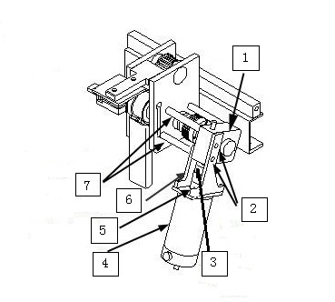
Figure 1. Interim Drive Assy
1
Gear Box
2
2 Long Screws
3
2 Upper Set Screws Location
4
Motor
5
Separation Location
6
Inner Bracket
7
Aluminum Spacers
CAUTION
Ferrous Material Hazard!
Longitudinal Drive Motor contains ferrous material.
Holding this assembly too close to the magnet bore will
forcibly attract it to the magnet. To prevent possible bodily injury
or material damage, remove the longitudinal drive motor and mounting
bracket from the Magnet Room to install the new longitudinal drive
motor.
While one person holds onto the motor firmly with both hands,
the other person should remove flat-head screws and nuts that secure
the gear box to the bridge.
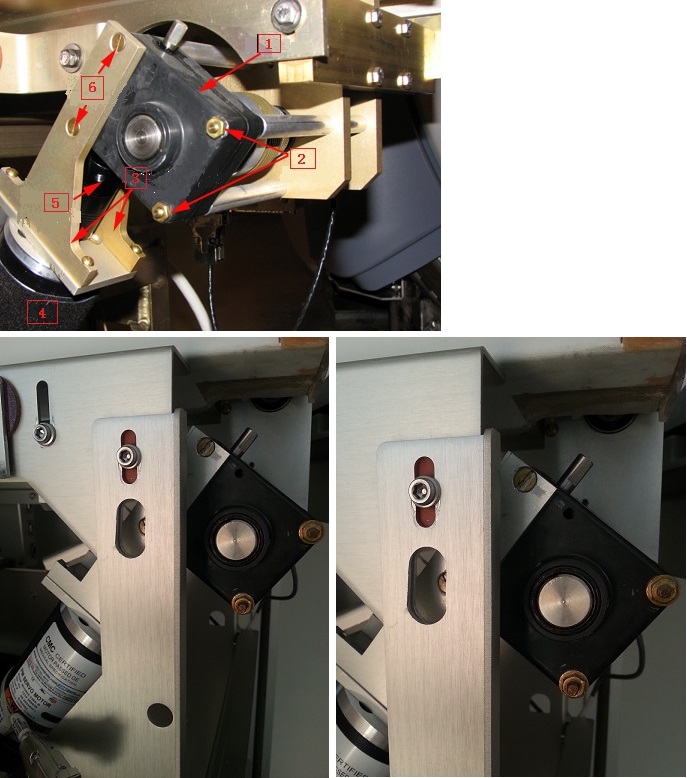
Figure 2. Mounted Drive Motor Assembly
1
Gear Box
2
Hex Nuts (2)
3
Motor Mounting Brackets
4
Motor
5
Flexible Coupling
6
Mounting Screws
With the last screw removed, take off the motor and its frame
from the bridge. Then carefully remove the motor from Magnet Room
by placing the motor on the floor and against the wall farthest from
the magnet. The service path to take the motor out of the scan room
is shown in Figure 3.
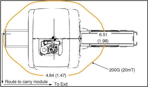
Figure 3. 200G Line and Route to Carry Module
With the motor outside of
the Magnet Room, remove the frame and coupling. Replace the failed
motor with the new one.
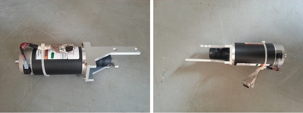
Figure 4. Motor
Carefully bring the motor and bracket assembly into the Magnet
Room along the same path used to remove the assembly.
To reinstall the motor and bracket assembly in the Rear Pedestal,
ensure that a second person holds onto the motor firmly with both
hands, while the first person reconnects the motor and bracket assembly
to the gear assembly. Tighten the screws and nuts to secure the motor
frame.
Tighten the two set screws on the coupling to finish the motor
installation. Make sure one of the hex set screws must be in front
of axis flat to prevent free rotation under the load.
Reattach the cables to the motor and the cover to the pedestal.
Remove LOTO and restore system power.
Gear Box Assembly Replacement
Procedure
Perform LOTO on the PDU. See the MR Service Safety Manual, PN 5452735.
Remove the rear pedestal left side cover (as viewed from the
rear of the magnet).
Disconnect the cables from the motor.
Loosen the two upper set screws on the coupling between motor
and gear box. Rotate the motor axis and coupling by hand in order
to get an access to both hex screws on the coupling. See Figure 1.
CAUTION
Ferrous Material Hazard!
Longitudinal Drive Motor contains ferrous material.
Holding this assembly too close to the magnet bore will
forcibly attract it to the magnet. To prevent possible bodily injury
or material damage, remove the longitudinal drive motor and mounting
bracket from the Magnet Room to install the new longitudinal drive
motor.
While one person holds onto the motor firmly with both hands,
the other person should remove flat-head screws and nuts that secure
the gear box to the bridge. See Figure 2.
With the last screw removed, take off the motor and its frame
from the bridge. Then carefully remove the motor from Magnet Room
by placing the motor on the floor and against the wall farthest from
the magnet. The service path to take the motor out of the scan room
is shown in Figure 3.
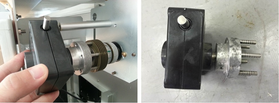
Take off the gear box together with half of its clutch. The
clutch connecting the gear box and the shaft can be pulled in half
in axial direction.
Figure 5. Take off Gear Box
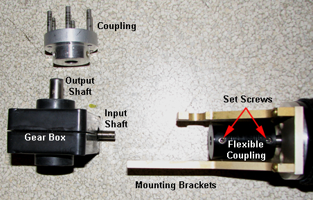
Loosen the two set screws and remove the half clutch.
Figure 6. Disassembled Drive Motor Assembly
Install the new gear box in a reverse sequence. Make sure one
of the hex set screws must be in front of axis flat to prevent free
rotation under the load.
Carefully bring the motor and bracket assembly into the Magnet
Room along the same path used to remove the assembly.
To reinstall the motor and bracket assembly in the Rear Pedestal,
ensure that a second person holds onto the motor firmly with both
hands, while the first person reconnects the motor and bracket assembly
to the gear assembly. Tighten the screws and nuts to secure the motor
frame.
Tighten the two set screws on the coupling to finish the motor
installation. Make sure one of the hex set screws must be in front
of axis flat to prevent free rotation under the load.
Reattach the cables to the motor and the cover to the pedestal.