
- SIGNA MR355 / SIGNA MR360
- Service Manual
- 5856356-3EN Revision 5.0
- Basic Service Documentation. Copyright General Electric Company.
- 00000018WIA300F7F20GYZ
- id_131075612.0
- Jul 19, 2019 10:59:37 AM
Longitudinal Drive Calibration
Prerequisites
| Required persons | Preliminary requirements | Procedure | Finalization |
|---|---|---|---|
| 1 | Not Applicable | 30 minutes | Not Applicable |
| Item | Quantity | Effectivity | Part number | Manufacturer |
|---|---|---|---|---|
| A nonferrous scale that can accurately measure 800mm or more | 1 | - | - | - |
| ||||
About this task
See Longitudinal Drive Calibration Overview for and overview of this procedure.
LONGITUDINAL DRIVE CALIBRATION
About this task
Note:
Longitudinal Drive Calibration must be performed before the Electrical Isocenter Calibration procedure.
Note:
During Load From Cold, Begin of cradle travel should have been set to 50 and End of travel set to 2568. This procedure assumes this starting point. If values are different, change them back to 50 and 2568, and download the TPS/ISE before continuing, procedure for Configuration File.
Procedure
- Attach the tie-wrap on the cradle with tape as a measuring meter. Record
the current position as A1. See Figure 1.
Figure 1. MARKING/INDEXING REFERENCE POINT A1 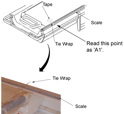
Table 4. Data Sheet A1= A2= DD: Travel Distance of Magnet Display = DA: A2-A1= - Record the current meter position as A2. See Figure 2. A2-A1 equals to the actual table movement (DA).
Figure 2. READING POINT A2 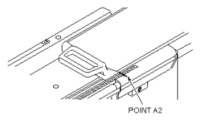
Parameter Setting of Table end Travel
Procedure
- Select “Common Service Desktop” and run Config File Manager. Refer to Configuration File Manager
- Search file for 2568mm travel parameters by scrolling down with the Enter button.
- Change the parameter end Travel to from 2568mm to the calculated vale.
- Save and close.
- Repeat the procedure from the beginning and verify that the specification is satisfied. (Specification |DA-DD| ≤ 1mm ) .
Finalization
No finalization steps.