
- SIGNA™ Hero 3.0T Service Methods
- 5852800-8EN Revision 1.0
- 00000018WIA3081A760GYZ
- id_20323521.22
- Jan 19, 2022 12:09:39 PM
Installing the 1-piece bridge
Install the 1-piece bridge assembly.
Prerequisites
| Tools and test equipment | |||
|---|---|---|---|
| Item | Quantity | Part number | Manufacturer |
| Nonmagnetic Titanium Service Tool Kit, Small Set | 1 | 5113258 | - |
| Replacement parts | |||
|---|---|---|---|
| Item | Quantity | Part number | Manufacturer |
| One Piece RTM Motus Bridge Assembly - RIO Enclosure | 1 | 5948000-100 | - |
Procedure
- From the patient end of the magnet, with a partner, lift the 1-piece bridge assembly into place, position the rollers on the rail, and slide the bridge assembly partially into the bore.
Figure 1. Position the 1-piece bridge 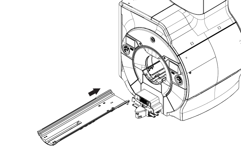
CAUTION - On the service end, connect cable M3507 to the end of the travel switch.
Figure 2. Connect M3507 to the travel switch 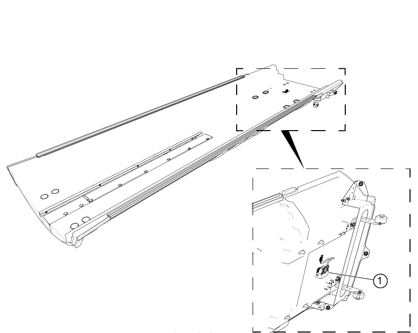
1 Travel switch connector - On the service end, install the UTNS antenna assembly to the 1-piece bridge.
- Position the BNC adapter on the bracket.
- Install the washer.
- Install the nut.
Figure 3. UTNS antenna components 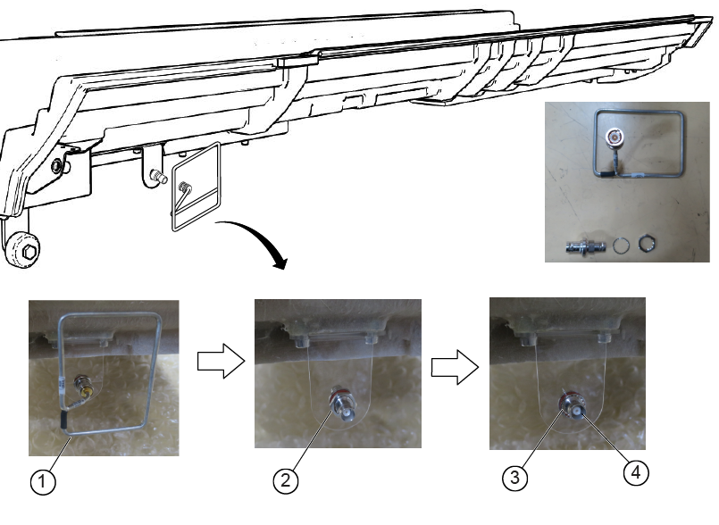
1 BNC adapter 2 Washer 3 Nut 4 UTNS antenna - Install the eight washers, eight screws, and eight caps (four on each end) to secure the 1-piece bridge assembly.
Figure 4. Attachment locations 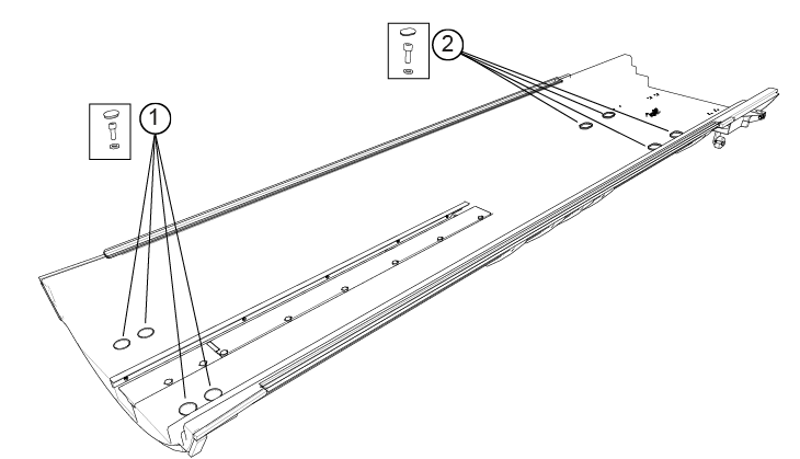
1 Washers, screws, caps 2 Washers, screws, caps - To determine the scan range configuration:
(For replacement procedures) Inspect the 1-piece bridge being replaced to determine if the hard stop support block is installed. Make sure the scan configuration is correctly set following the finalization procedures in Setting the patient table scan range configuration.
(For new installations) Follow the procedures in Running ICW Installation Mode, and reference Setting the patient table scan range configuration.
Figure 5. Hard stop support block location 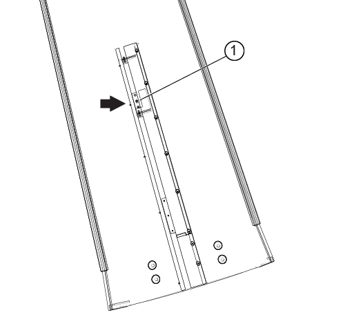
1 Hard stop support block