- SIGNA™ Hero 3.0T Service Methods
- 5852800-8EN Revision 1.0
- 00000018WIA3071A760GYZ
- id_20323511.13
- Jan 26, 2022 12:38:41 PM
Removing the 1-piece bridge
Remove the 1-piece bridge assembly.
Prerequisites
| Required conditions |
|---|
| Electrical Safety |
Procedure
- On the service end, remove the UTNS antenna assembly and retain the parts for installation on the replacement bridge.
- Remove the nut securing the BNC adapter.
- Remove the washer from the BNC adapter.
- Remove the BNC adapter from the bracket.
Figure 1. UTNS antenna components 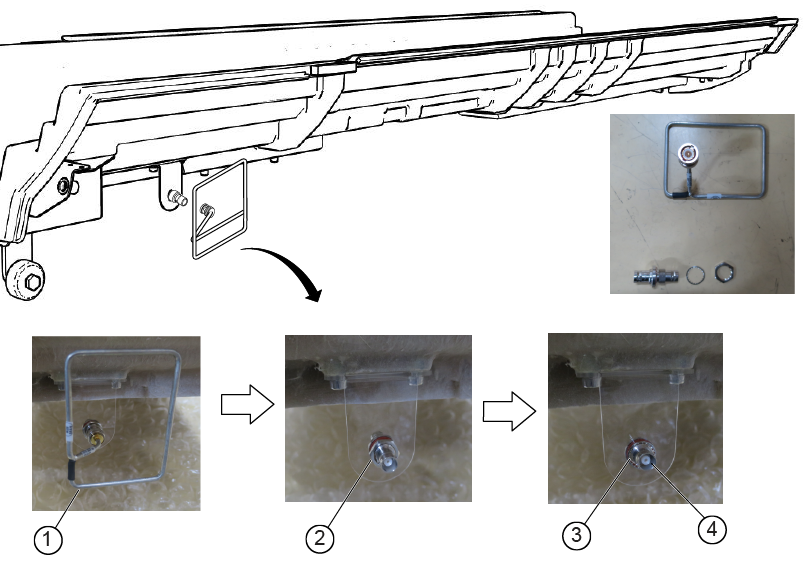
1 UTNS antenna 2 Nut 3 Washer 4 BNC adapter - On the underside of the bridge assembly, disconnect cable M3507 from the end of the travel switch connector.
Figure 2. Travel switch connector location 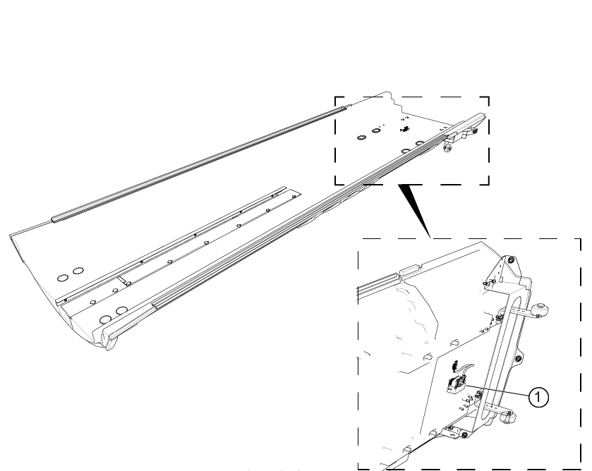
1 Travel switch connector - Remove the eight screw covers and eight screws (four on each end) securing the 1-piece bridge assembly.
Figure 3. Attachment locations 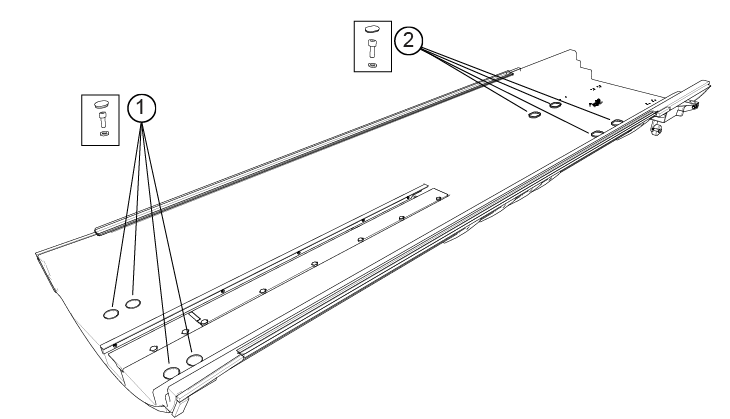
1 Patient end 2 Service end - With two people: on the service end, one person lifts the end of the bridge up until the rollers are clear of the edge of the bore. From the patient end, the second person pulls the 1-piece bridge forward until the rollers can rest on the rails.
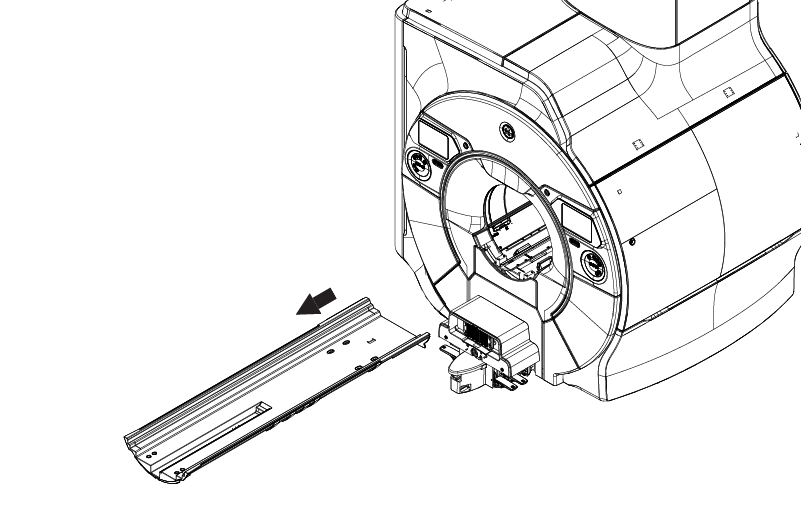
CAUTION Figure 4. Lift the rollers onto the bore 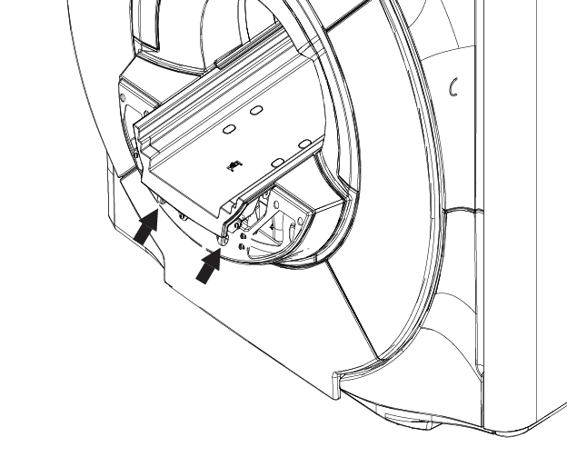
- On the patient end, with two people, remove the bridge assembly and carefully put it on the floor away from the magnet.
Figure 5. Removing the 1-pc bridge