
- SIGNA™ Hero 3.0T Service Methods
- 5852800-8EN Revision 1.0
- 00000018WIA306BA230GYZ
- id_156673391.25
- Oct 18, 2021 2:52:52 PM
Body Coil Mount and Base Plate (Front) Replacement
Prerequisites
| Required persons | Preliminary requirements | Procedure | Finalization |
|---|---|---|---|
| 2 | Not Applicable | 2 hours | 60 minutes |
| Item | Quantity | Effectivity | Part number | Manufacturer |
|---|---|---|---|---|
| Nonmagnetic Titanium Service Tool Kit, Large Set | 1 | - | 5112581 | - |
| Cut-Resistant Gloves | 1 | - |
| - |
| non-magnetic small level | 1 | - |
| - |
| Item | Quantity | Effectivity | Part number | Manufacturer |
|---|---|---|---|---|
| Front Body Coil Mount | 1 | - |
Refer to FRU manual | - |
| ||||
About this task
Overview
Use this procedure to replace the body coil mount and base plate (front).
Body Coil Mount Front Assembly Removal
Procedure
- Remove the dock interface cover.
Figure 1. Removing the dock interface cover 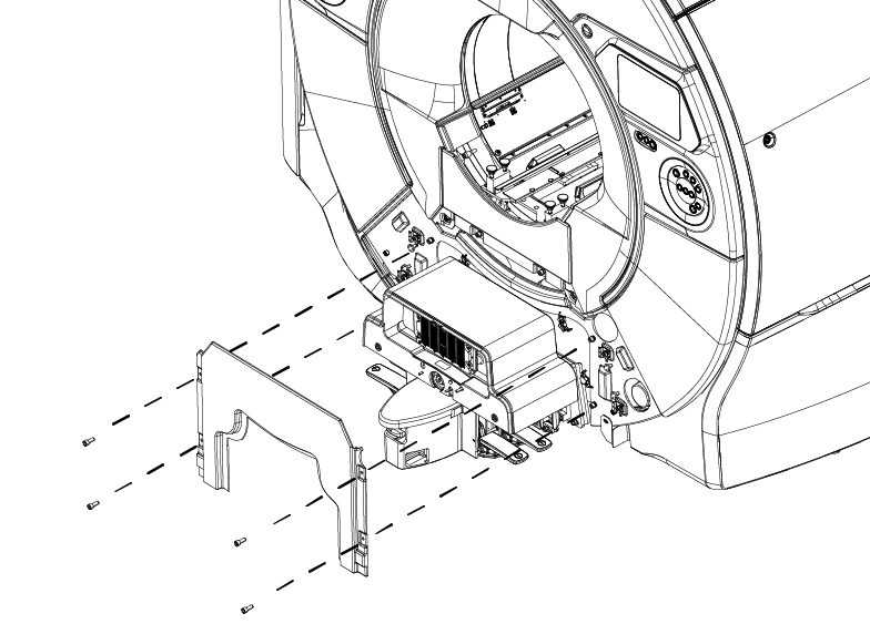
- Disconnect the two (2) cooling air ducts at the rear end of the body coil.
Figure 2. Disconnecting the cooling air ducts 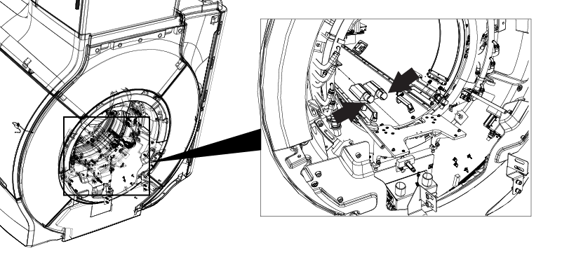
- Disconnect the HART ID cable at the rear end of the body coil.
Figure 3. Disconnecting the HART ID cable 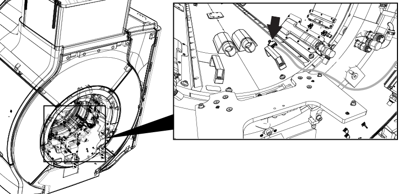
- Disconnect the CH1 and CH2 drive cables from the RF body coil in the rear.
Figure 4. Disconnecting the CH1 and CH2 drive cables 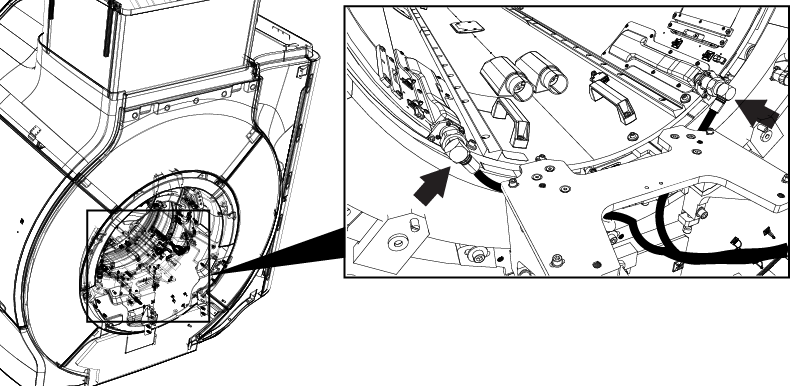
- Disconnect the bore light cable connectors. (Front End: 2 connectors, Rear End: 2 cables)
Figure 5. Disconnecting the rear bore lights 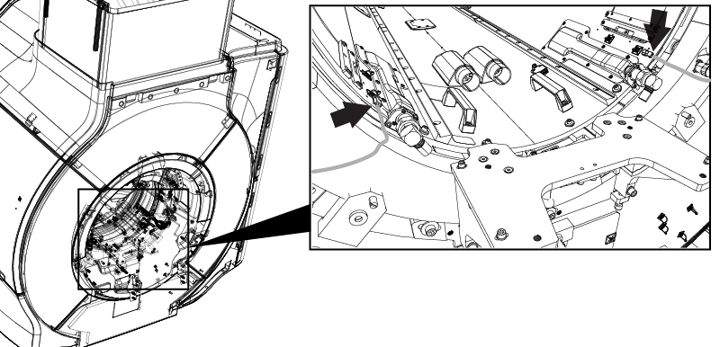
Figure 6. Disconnecting the front bore lights 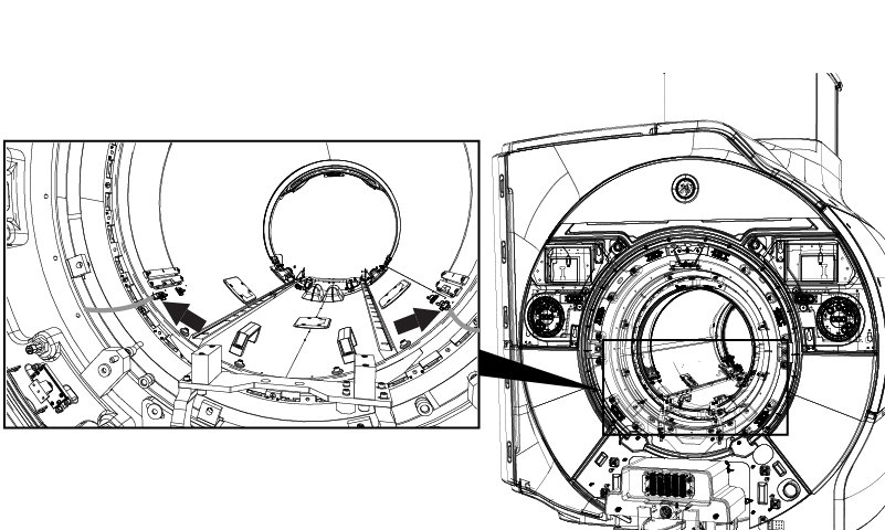
- At rear end of the magnet, remove four M6 bolts and washers securing the RF body coil.
Figure 7. Removing the M6 bolts and washers 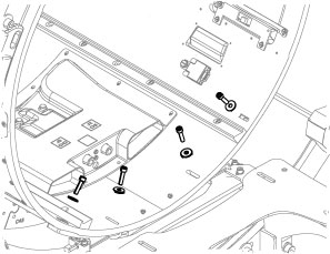
- On the front end of the magnet, remove four M6 bolts and washers from the bases of RF coil centering assembly.
Figure 8. Removing the RF coil centering assembly bolts 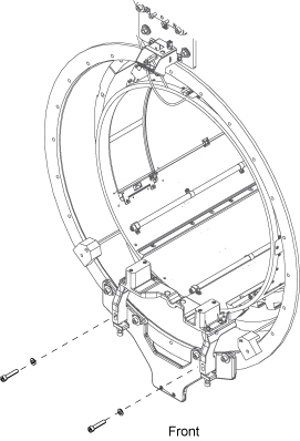
- Remove the air flow sensors and tape them to the magnet enclosure in a position that will not interfere with the body coil removal.
Figure 9. Removing the air flow sensors 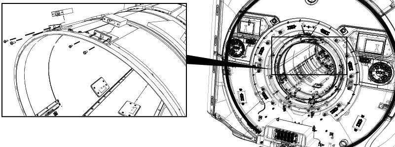
From the front of the magnet, pull the body coil forward until the front end is outside the bore.CAUTION 
Figure 10. Moving the body coil 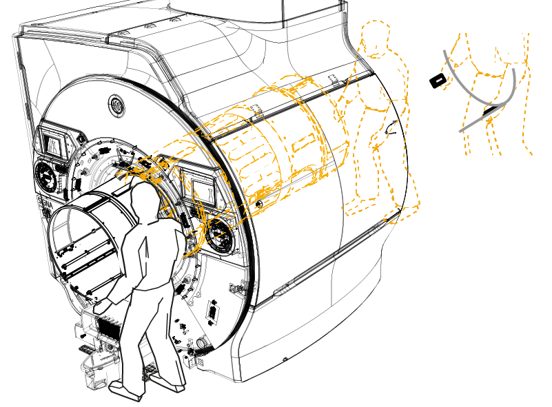
- Remove the four M6 screws and large glass laminate washers. Remove the body coil mount front assembly.
Figure 11. Removing the RF coil body coil mount front assembly 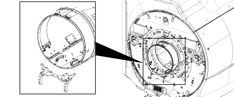
Front Base Plate Replacement
Procedure
Confirm the front base plate is not damaged. If the front base plate is not damaged or body coil mount is not replaced from old type to new type, skip this section and go to Restoration.Notice 
Move the body coil location back create enough clearance to access the base plate.CAUTION - Remove the lower mounting block by removing two screws and washers on the magnet front end.
Figure 12. Lower mounting block removal (magnet front) 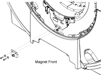
- Mark the alignment lines for the base plate on the magnet.
Figure 13. Marking bracket alignment 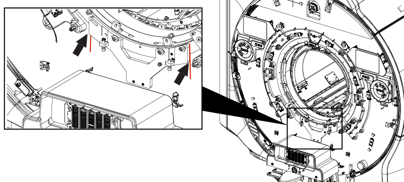
- Remove the original base plate.
Figure 14. Removing the base plate 
- On the new base plate, adjust the height of screw to make the height approximately equal to the original base plate. Then, tighten the lock nuts. Note: This adjustment is the rough adjustment for centering the body coil in the magnet bore. Fine adjustment will be done in body coil isolation procedure later. There is no specification in this step.
-
A≒A’
-
B≒B’
Figure 15. Adjusting the screw height 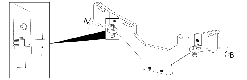
-
- Attach the leveling block to the base plate with two screws (1000-M10C35-33).
Figure 16. Attaching the leveling block 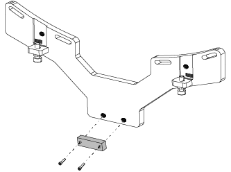
- Align and install the new front base plate on the Magnet with four screws (1000-M10C45-33) and washers (2000-M10C-10). 2000-M10C-10
Figure 17. Installing the base plate 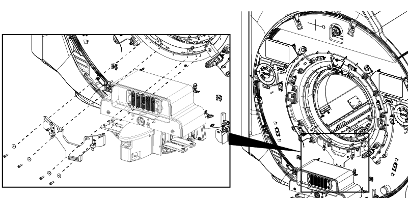
- Place the non-magnetic level on the level block and confirm that the level bubble is centered between the lines. If not, loosen the four screws and level the base plate position.
Figure 18. Leveling the front base plate 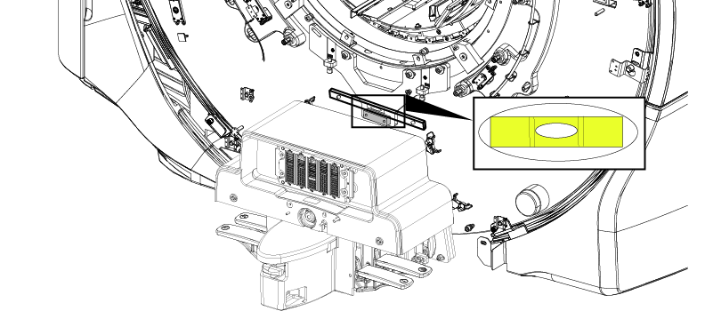
Move out the body coil slightly.CAUTION Figure 19. Moving the body coil
Restoration
Procedure
- Restore the new body coil mount front assembly.Note: If the body coil was not replaced, reuse the original screw and washer.
If the body coil is replaced, use the large glass laminate washers (5988407) and M6x30 screws (1000-M6C030-33) included in the body coil FRU.
Figure 20. Attaching the front mount
Restore the body coil to the original location.CAUTION Figure 21. Installing the body coil - Connect the front bracket to the base bracket.
Figure 22. Securing the front end of the body coil 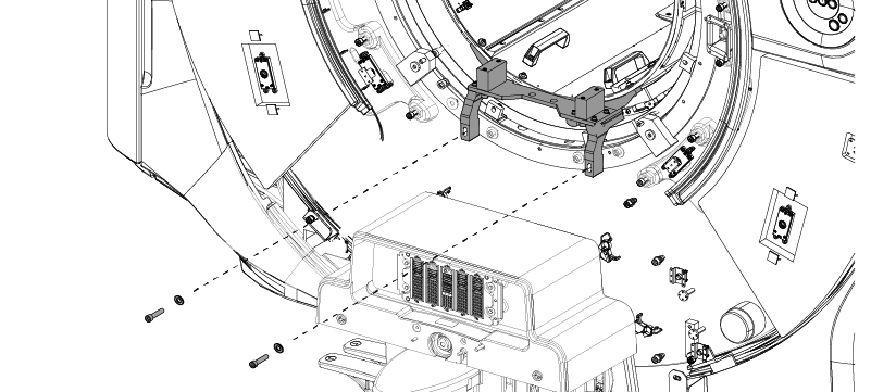
- Secure the body coil to the rear bracket with four M6 bolts and washers.Note: If the body coil is not replaced, reuse the same washers and screws which were originally used for fixing the rear of the body coil.
If the body coil is replaced, use the large glass laminate washers (5988407) and M6x30 screws (1000-M6C030-33) which are included in body coil FRU.
Figure 23. Securing the rear end of the body coil 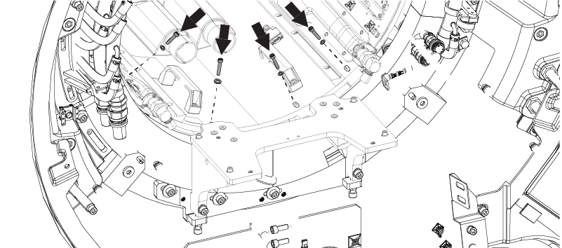
- Reconnect the bore light cable connectors. (Front End: 2 connectors, Rear End: 2 cables)
Figure 24. Reconnecting the rear bore light connections Figure 25. Reconnecting the front bore light connections - Reconnect the bore light cable connectors. (Front End: 2 connectors, Rear End: 2 cables)
Figure 26. Reconnecting the rear bore light connections Figure 27. Reconnecting the front bore light connections - Restore the air flow sensors.
Figure 28. Reconnecting the air flow sensors - Restore the two (2) cooling air ducts at the rear end of the body coil.
Figure 29. Reconnecting the cooling air ducts - Reconnect the CH1 and CH2 drive cables to the RF body coil.
Figure 30. Disconnecting the CH1 and CH2 drive cables - Restore the dock interface cover.
Figure 31. Dock interface cover - Restore the right and left side covers.
Figure 32. Right and left side covers 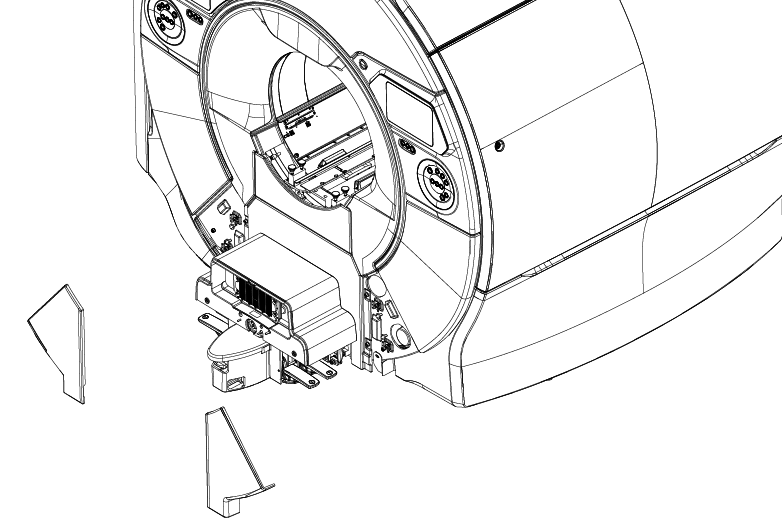
Finalization
Procedure
- Remove LOTO. Refer to Removing LOTO - ISC.
- Move the table up and restore the dock interface cover.
- Perform Dual Drive Quadrature Calibration. Refer to Dual drive quadrature tool.
- Perform the system performance test (SPT).