
- SIGNA™ Hero 3.0T Service Methods
- 5852800-8EN Revision 1.0
- 00000018WIA30D15280GYZ
- id_20335052.2
- Jan 27, 2022 6:43:59 PM
Replacing the IRD fiber optic cables
The procedure for replacing the IRD fiber optic USB and DP cables.
Prerequisites
| Personnel requirements | |||
|---|---|---|---|
| Required persons | Preliminary requirements | Procedure | Finalization |
| 2 | - | 6 hours | 10 minutes |
| Consumables | |||
|---|---|---|---|
| Item | Quantity | Part number | Manufacturer |
| Self-locking Cable Tie
or Cable Tie, Self-Locking | 1 | 46-208758P5
or 5343293 | - |
| Replacement parts | |||
|---|---|---|---|
| Item | Quantity | Part number | Manufacturer |
| Run P5006 Cable Harness, GOC to IRD Fiber Optic, contains 1 each of: | |||
| FRU, USB-AOC optic fiber cable, Host PC USB3.0 port to IRD-Right-J3, Run# P2027 48000 mm, GEN2 | 1 | 5778287-8 | |
| FRU, USB-AOC optic fiber cable, Host PC USB3.0 port to IRD-Left-J3, Run# P2029 48000 mm, GEN2 | 1 | 5778287-9 | |
| DP AOC, GOC DP Dongle to IRD Right DP, Run P2026 48000 mm | 1 | 5879076 | |
| DP AOC, GOC DP Dongle to IRD Left DP, Run P2028 48000 mm | 1 | 5879076-2 | |
| Safety |
|---|
|
Before working in any GE Healthcare MR suite or performing any GE Healthcare service procedure, you must:
If you have any safety concerns at any time, do not begin work or immediately stop work and move to a safe location. Immediately contact your supervisor or site safety officer for instructions on how to proceed. |
Before starting this procedure, GE recommends doing following:
- Make sure that the issue is resolved by directly connecting the cables from the IRD to the Host PC.
- If any IRD cables or components are swapped for troubleshooting, return them to their original position.
Note: Depending on the routing of the IRD cables, you may need to remove ceiling panels from the MR room, corridor, or operator room. Please notify and consult with the customer regarding the ceiling panel removal and other locations impacted by this procedure.
Procedure
- Route the new IRD cable(s) the same way as the existing IRD cable harness is routed starting from the IRDs in the magnet room. Note: To connect the cables to the IRD, follow the instructions in Installing the magnet left and right control panel covers.
Figure 1. IRD cable routing in the magnet room 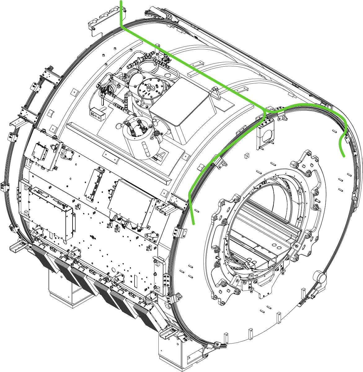
Finalization
- Make sure all system interconnects are returned to normal configurations.
- Do a check scan. See Doing a check scan.