• Discovery MR750w and SIGNA™ Architect T 3.0T System Service Methods
  • 5690002-2EN Revision 4
  • Object ID: 00000018WIA3040FD20GYZ
  • Topic ID: id_13106387 Version: 5.1
  • Date: Jul 13, 2021 6:26:23 PM

3.0T HD Breast Array Coil FRUs and Replacements

Prerequisites

Table 1. Personnel requirements
Required personsPreliminary requirementsProcedureFinalization
1Not Applicable45 minutesNot Applicable
Table 2. Tools and test equipment
ItemQuantityEffectivityPart numberManufacturer
Standard tool set1---
ESD kit with monitor1---
Table 3. Consumables
ItemQuantityEffectivityPart numberManufacturer
Nylon cable ties (2)1---
Table 4. Replacement parts
ItemQuantityEffectivityPart numberManufacturer
A-port FRU output cable assembly, 3T breast coil1RRx receive chain systems

2417366

-

About this task

This document contains the cable replacement procedure for the HD breast coil Cable Replacement Procedure and the field replaceable units for the HD breast coil Field Replaceable Units and Additional Accessories.

Topic ID: id_SL1985609-1061489

Cable Replacement Procedure

Procedure

  1. Remove the coil from the magnet room. Wear the ESD wrist strap to avoid electrostatic discharge.

    Systems with the RRx receive chain use the A-port system cable and four P-port connections.

  2. Position the coil so that the bottom side faces upward.
    Figure 1. Coil Bottom
  3. Remove all screws.
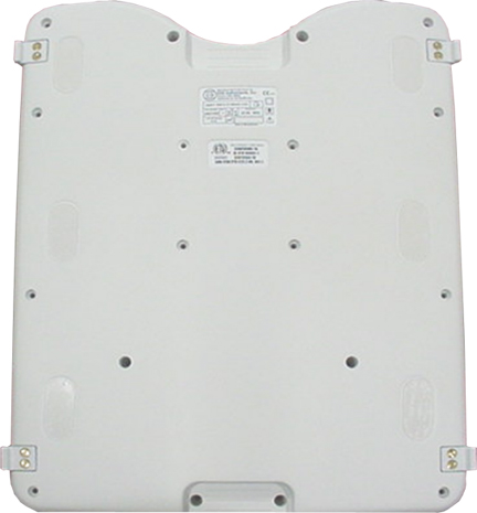
  4. Remove the cable from the coil.
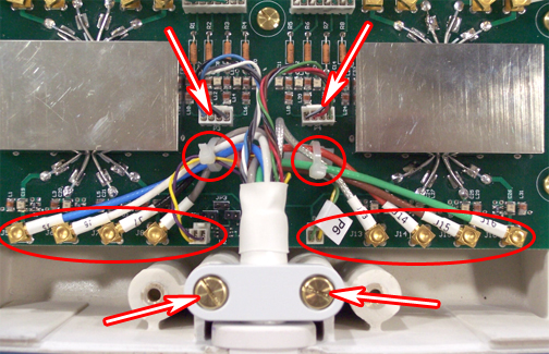
    1. Remove the cable ties.
      Figure 2. Cable Connections RRx System
    2. Disconnect all RF cables and DC cables.
    3. Remove the cable clamp from the coil.
    4. Remove the cable assembly.
  5. Install the new cable:
    1. Attach the new cable assembly by sliding the strain relief of the cable into the cutout of the housing, with its round section toward the bottom. Press the strain relief down firmly, so that the edge of the housing fits into the groove of stain relief.
    2. Reinstall the cable clamp.
    3. (For A-port system cable) Install all channel connections (8 coaxial and 4 DC connectors) by matching the designators on the cable with the designators on the PCB.
      • Tie cables J5, J6, J7, J8, and P5 to the left cable tie holder on the PCB.

      • Tie cables J13, J14, J15, J16, and P6 to the right cable tie holder.

      • Route the cables as shown in Figure 2, so none of them touch the rectangular shield.

      • Cables P3 and P4 should not be tied.

    Table 5. Cable Connections
    RF wires
    ColorLabel
    BlueJ5
    WhiteJ6
    BlackJ7
    GrayJ8
    ClearJ13
    RedJ14
    BrownJ15
    GreenJ16
    DC wires
    ColorLabel
    Gray, black, white, blue (twisted)P3
    Green, brown, red, black/white (twisted)P4
    Purple, yellow (twisted)P5
    Yellow/white, green/white (twisted)P6
  6. Reinstall the coil cover.
Topic ID: id_SL1985614-1061489

Field Replaceable Units and Additional Accessories

Procedure

  1. Refer to the following table for the HD breast coil field replaceable units (FRUs).
    Table 6. Field Replaceable Units
    Description Part #
    3.0T breast w/o cable2417367
    A-port output cable assembly, 3.0T breast coil2417366
    Phantom assembly, 3.0T breast biopsy2417234
    Breast coil headrest2412281
    Assembly, 1.5T breast coillateral2414541
    Assembly, 1.5T breast coillateral2412285
    3.0T 10cm spherical phantoms2360034
    Phantom positioner, breast5343432
    FRU, 3T breast coil P-port5404749
  2. Refer to the following table for additional accessories for the HD breast coil.
    Table 7. Additional Accessories (Not FRUs)
    Description Part #
    Plate, lateral breast compression2414543
    Plate, medial breast compression2414544
    Sterilized breast coil medial biopsy2414342
    Sterilized breast coil lateral bio2414346
    Body pad, 3.0T breast biopsy coil2417270
    Trans pad, 3.0T breast biopsy coil2417271
    Compress pad, breast biopsy coil2417269
    Assembly, breast coil chamber cover2414341
Topic ID: id_14931434

Finalization

Finalization

No finalization steps.