
- Discovery MR750w and SIGNA™ Architect T 3.0T System Service Methods
- 5690002-2EN Revision 4
- 00000018WIA30A4DE20GYZ
- id_131058692.0
- Feb 22, 2021 1:47:21 AM
3.0T General Purpose Flex Coil
Introduction
Product Identification and Shipping List
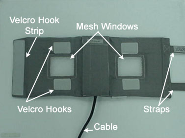
The 3.0T General Purpose (GP) Flex Coil consists of one major assembly shown below. The unit is 22 in (55.6 cm) long (not including straps) by 9 in (22 cm) wide. It has two mesh windows that indicate the open center of the two coils and aid in positioning. Two 31 in (78.5 cm) straps are attached to one end of the coil fabric. The undersides of these straps are covered with Velcro that attach to a Velcro hook strip at the other end of the coil, and to four Velcro hooks located above and below the mesh windows. A 72 in (183.3 cm) RF cable exits the material on one of the long sides and has a BNC connection that attaches to the surface coil quick disconnect box.
| Description | GE Part Number | Quantity |
| 3.0T GP Flex Coil | 2373366 | 1 |
| Operator Manual | 2373326-299 | 1 |
Environmental Requirements
Storage and transportation conditions:
-
Ambient temperature range of –40 °F to +158 °F (–40°C to +70 °C)
-
Relative humidity range of 40% to 95%, non-condensing
-
Atmospheric pressure range of 525 hPa to 1013 hPa
Dimensions: 21.9 in x 8.7 in x 1.6 in (55.6 cm x 22 cm x 4 cm) (excluding cable assembly)
Strap length: 31 in (78.5 cm)
Weight: 1.3 lb (575 g) maximum
Theory of Operation
The 3.0T GP Flex Coil design is a linear, receive-only flexible coil. It consists of two loops that are serially connected to create a co-rotating, saddle coil pair. If the loops are positioned in a more open fashion (that is, they move farther away from each other toward a planar or flat configuration), the image uniformity decreases. For close positioning, do not overlap the coil ends. Doing so will not damage the coil, but performance will suffer.
When aligned properly, this saddle design provides exceptional uniformity across the sensitive volume of the coil and a minimum of bright spots or high-intensity areas. For optimal positioning, the circular shape should be maintained with the two mesh windows 4 in (10 cm) apart and the coil ends 2 in (5 cm) apart. Some deviation from the optimal position does not significantly degrade the uniformity. Therefore, this coil can be used in anatomical areas such as the hip, brachial plexus, larger knees, or ankle.
-
The coil consists of one major assembly shown in Figure 1. The two loops are in a flexible material covered with fabric. This allows the coil to bend in one direction, making it easy to wrap around the anatomy of interest.
-
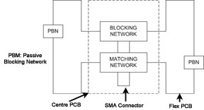
The block diagram of the antenna electronics is shown in Figure 2. The two flex PCB wings on either side of the rigid PCB form the loops. The rigid PCB has a matching network that matches the loaded antenna to 50 ohms and an active blocking network. The blocking network consists of a single PIN diode and a tuned LC network. The diode is forward biased whenever the body coil transmits. The external cable is connected to the antenna at a right angle SMA jack. The flex PCB has passive blocking networks that consist of a Schottky diode and a tuned LC network.
Setup and Calibration
Coil Installation
Installation
The name for this coil is: GPFlex. No installation steps are required.
Positioning
When positioning the coil around a phantom or anatomy, do not overlap the ends. Use pads as necessary.
Coil Performance Check
Perform coil imaging verification (system level SNR check). See Coil Imaging Performance Verification.
Periodic Quality Assurance Check
On a periodic basis, such as during planned maintenance, perform these quality assurance checks to ensure the coil is operating properly.
-
Check external cable for cracks or cuts.
-
Perform coil imaging verification (system level SNR check). See Coil Imaging Performance Verification and record the data values in the data sheet.
Functional Checks
Scanner Verification
Perform a system level SNR check. See Coil Imaging Performance Verification.
Coil Imaging Performance Verification
Tools Required
| Description | GE Part Number | Quantity |
| Head TLT Sphere (Doped Silicon) | 2359877 | 1 |
| QA Load Phantom | 2360031 | 1 |
| GP Flex Coil Adapter | 5176311 | 1 |
| Curved Panel Adapter Assembly (for Flat Table) | 5395828 | 1 |
Procedure Overview
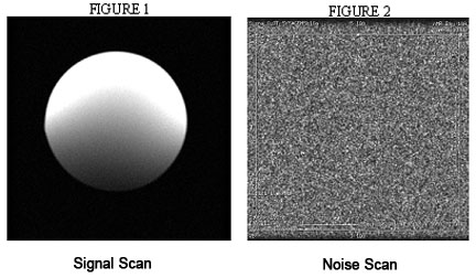
SNR measurements for the GP flex coil require sets of signal and noise scans. Refer to the data sheet in SNR Data Sheet to understand the data required to calculate the SNR.
The image quality check uses two different protocols for signal and noise image acquisition. The signal scan is an FSE sequence used to minimize susceptibility and B0 inhomogeneity effects. The noise scan is a GRE sequence that has a Control Variable (do_noise) to eliminate the transmit RF completely during the scan. The signal scan must be run before the noise scan because the R1, R2, and TG values from the signal scan are used for the noise scan.
Signal Scan
-
Remove the quad head coil from the cradle before performing any body or surface coil scans. Failure to do this may result in damage to the quad head coil T/R network.
-
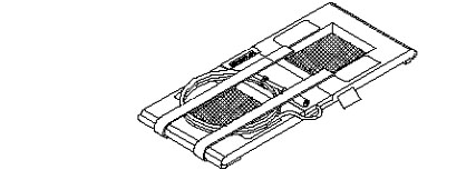
(For flat table) Insert the curved panel adapter assembly in the magnet end of the table.
Figure 3. Curved Panel Adapter Assembly 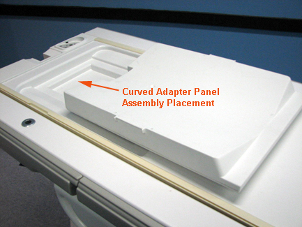
-
At the magnet, press the Alignment Light button to turn on the light. Move the cradle to align the coil to the alignment light, and press Landmark to landmark the alignment.
Figure 4. Landmark and Alignment 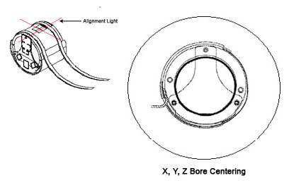
-
Move the coil into the scan position by pushing the Move to Scan button; ensure the cable does not get snagged.
-
At the console, set the protocols according to the table below.
Table 3. Signal Protocols Patient/Exam Information ID: geservice Name: GP Flex Coil Patient Weight: 111 lb (50 kg) A/P Center, R/L Center: 0.0 Table Delta: 0.0 Patient Position Patient Position: Supine Patient Entry: Head First Coil: HD GE General Purpose Flex Coil Series Description: Signal Imaging Parameters Plane: Axial Mode: 2D Pulse Seq: FSE-XL Chem SAT: None Contrast: <leave blank> Scan Timing # TE(s) per Scan: 1 TE: 17 TR: 750 Echo Train Length: 4 Bandwidth: 15.63 Acquisition Timing Freq: 256 Phase: 256 NEX: 1 Phase FOV: 1.00 Freq. DIR: R/L Shim: Auto Phase Correct: On Table Delta: 0.00 Scanning Range FOV: 24 Slice Thickness: 5 Spacing: 13.8 A/P Center, R/L Center: 0.00 S/I Start: S0 S/I End: I0 # Slices: 5 -
Click Save Rx to download the protocols, then click Prepare to Scan.
-
Run Auto Prescan. Record the R1, R2, and TG values on the SNR data sheet in SNR Data Sheet.
-
Run Scan.
Noise Scan
A signal scan must be run before the noise scan because the same R1, R2, and TG values must be used for both the signal and noise scans. Do not run an Auto Prescan before the noise scan because the values will be changed.
-
Copy the signal scan series. Use Copy Series (highlight signal series and right-click) and Paste Series in Rx Manager.
-
Click Setup and set the protocols as shown in Table 4.
-
Click Save Rx.
-
Open the Display CVs menu under . Set the rhformat and do_noise CVs to 1.
-
Run Manual Prescan. Do not make any changes.
-
Click Done.
-
Run Scan.
| Patient Position | |
| Patient Position: | Supine |
| Patient Entry: | Head First |
| Coil: | HD GE General Purpose Flex Coil |
| Series Description: | Noise |
| Imaging Parameters | |
| Plane: | Axial |
| Mode: | 2D |
| Pulse Seq: | GRE |
| Chem SAT: | None |
| Contrast: | leave blank |
| Scan Timing | |
| # TE(s) per Scan: | 1 |
| TE: | Min Full |
| TR: | 34 |
| Flip Angle: | 1 |
| Bandwidth: | 15.63 |
| Acquisition Timing | |
| Freq: | 256 |
| Phase: | 256 |
| NEX: | 1 |
| Phase FOV: | 1.00 |
| Freq. DIR: | R/L |
| Shim: | Auto |
| Phase Correct: | Off |
| Table Delta: | 0.00 |
| Scanning Range | |
| FOV: | 24 |
| Slice Thickness: | 5 |
| Spacing: | 0 |
| A/P Center, R/L Center: | 0.00 |
| S/I Start: | S0 |
| S/I End: | I0 |
| # Slices: | 5 |
| Table Delta: | 0.00 |
SNR Image Analysis
SNR Measurement
Regions of interest in both signal and noise images can be measured directly in the image browser. Click Measure, select the circular or rectangular shape, and adjust its size and orientation when the shape is displayed in the selected image. The mean, standard deviation, and area of ROI are displayed in the lower right corner of the image.

The SNR calculation uses the mean of the signal image and standard deviation of the noise image. SNR is measured for each element, not on the composite image.
For the signal measurement, choose an ROI covering approximately 80% of the phantom. Also measure the noise with an ROI covering 80% of FOV. ROI should be taken as circle centered at the phantom. Examples of typical ROIs are shown below.
SNR Specification
The SNR measurements must be greater than or equal to the specification in the table below.
| Slice Location | Image Number | SNR |
| S37.5 | 3 | 68 |
| S0 | 3 | 90 |
| 137.5 | 3 | 68 |
External Cable Check
-
Select the diode test function on the digital multimeter (DMM).
-
Connect the positive lead of the DMM to the center pin of the BNC on the external cable, and connect the negative lead to the main housing/ground of the BNC.
Figure 6. BNC Connector 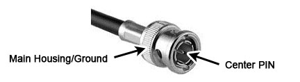
-
Flex the external cable, especially near the connectors and the strain relief, and verify that a reading of 0.400 to 0.600 remains on the DMM with no instability or fluctuations.
-
Connect the positive lead of the DMM to the main housing/ground of the BNC on the external cable, and connect the negative lead to the center pin of the BNC.
-
Flex the external cable, especially near the connectors and the strain relief, and verify that a reading of Infinity remains on the DMM with no instability or fluctuations.
-
If the cable fails any of the above tests, replace it. Refer to External Cable Replacement External Cable Replacement.
PIN Diode Check
There is only one PIN diode in this antenna. The following procedure determines if the PIN diode is defective.
| CAUTION | |
|---|---|
-
Select the Diode Test function on the DMM.
-
Connect the positive lead of the DMM to the center pin of the BNC on the external cable, and connect the negative lead to the main housing/ground of the BNC. See Figure 6.
Verify a reading of 0.400 to 0.600 on the DMM.
-
If a reading below 0.400 is observed in either direction, either the output cable is shorted or the PIN diode is defective.
-
If a reading above 0.600 is observed, the PIN diode is defective.
-
-
Connect the positive lead of the DMM to the main housing/ground of the BNC on the external cable, and connect the negative lead to the center pin of the BNC.
Verify a reading of Infinity on the DMM. If a reading of Infinity is observed in both directions, either the output cable is open or the PIN diode is open.
If the coil has a defective PIN diode, the respective component must be replaced.
Maintenance
Coil Care
| Warning | |
|---|---|
| CAUTION | |
|---|---|
If necessary, a 10% bleach solution can be used for more rigorous cleaning; however, some discoloration of the strap, cover, or pad may occur.
Special Care Requirements (If Applicable)
Contact GE-authorized service personnel for disposal of the coil at the end of product life.
Replacement
Simple removals that are clearly obvious are not described here. Unless otherwise noted, the steps for reassembly are the reverse order of the steps described for disassembly.
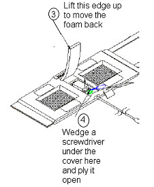
Assembly/Disassembly of Coil
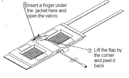
To reassemble the coil:
-
Place the cover back on the posts and press it until it snaps into place.
-
Push the foam flap under the jacket.
-
Carefully put the fabric flap into place, making sure the Velcro on the edges lines up with the Velcro on the jacket. Tuck the end of the flap under the jacket.
-
Press the Velcro while making sure no edges are left open.
External Cable Replacement
-
Disassemble the coil as instructed in Assembly/Disassembly of Coil. Unscrew the two nylon screws and remove the strain relief upper cover.
-
Unscrew (use two 8 mm wrenches, one on the circuit board female connector and one on the male cable connector), and remove the male SMA cable connector from the circuit board. Be careful not to twist the female SMA connector from the circuit board.
Figure 9. Replacing External Cable 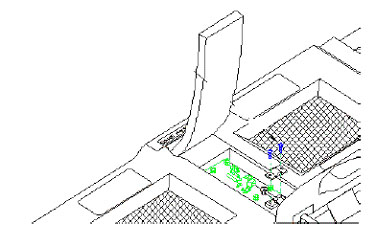
-
Remove the external cable from the coil.
-
Install the new cable. Stabilize the circuit board and the connector on the circuit board.
Note:Too much torque (>2 kgf-cm) can cause damage.
-
Reattach the strain relief, and reassemble the coil per Assembly/Disassembly of Coil.
Mechanical Hardware Replacement
-
Refer to Renewal Parts for the hardware kit part number.
-
To replace the cover assembly, refer to Assembly/Disassembly of Coil.
-
To replace the upper strain relief block and the two screws, refer to External Cable Replacement.
-
If a plastic standoff breaks, it can be pulled out using needle-nose pliers. Insert a new standoff in its place, making sure that the flat end goes in first.
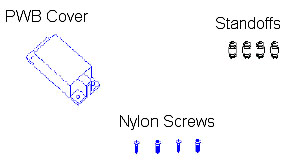
Figure 10. Replacing Mechanical Hardware 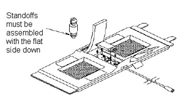
Renewal Parts
The table below lists the replaceable parts for the GP Flex Coil.
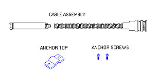
| Description | GE Part Number |
| 3.0T GP Flex Coil | 2373366 |
| Cable Kit | 2379330 |
| Hardware Kit | 2383558 |
| GP Flex Coil MR750 Adapter | 5176311 |
| Curved Panel Adapter Assembly (for flat table only) | 5395828 |
The items in this table are pictured below (adapters excluded).
SNR Data Sheet
Use the table provided in the PDF file below to record the calculated SNR data obtained in Functional Checks.