
- Discovery MR750w and SIGNA™ Architect T 3.0T System Service Methods
- 5690002-2EN Revision 4
- 00000018WIA30B5DE20GYZ
- id_131074563.2
- Apr 23, 2020 7:31:10 PM
HD T/R Quad Extremity Coil FRUs and Replacements
Personnel Requirements
| Required Persons | Procedure Timing |
| 1 | 30 minutes |
Overview
This document contains the FRUs, additional accessories, and spare kit components for the HD T/R Quad Extremity Coil by Invivo. It also contains replacement procedures for the FRUs. The coil replacement procedures are the same for all the following:
-
(For curved table)
Catalog M3335ME 1.5T coil
-
(For flat table)
Catalog M7000FT 1.5T coil
-
(For curved table)
Catalog M3335LP 3.0T coil
-
(For flat table)
Catalog M7000GT 3.0T coil
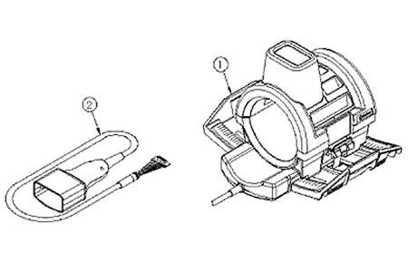
FRUs and Additional Accessories
The item numbers in the table refer to the FRU diagrams below.
| Item | Description | 1.5T | 3.0T | ||
| GE Part | Supplier Part | GE Part | Supplier Part | ||
| 1 | HD T/R Quad Extremity Assembly with Cable and Baseplate (for Curved Table) | 5147225-2 | 870323 | 5147137-2 | Invivo 4535-303-0519* |
| HD Quad Extremity Coil Assembly with Cable and Baseplate (for Flat Table) | 5406350-2 | 4535-303-0475* | 5406653-2 | 4535-303-0518* | |
| 2 | HD T/R Quad Extremity Cable Assembly | 5147225-6 | 870290 | 5147225-6 | 870290 |
| 3 | Coil Repair Kit I-3 (for Curved Table) | 2357819-10 | 14234 | 2357819-10 | 14234 |
| Coil Repair Kit I-4 (for Flat Table) | 5406350-10 | 4535-303-0343* | 5406350-10 | 4535-303-0343* | |
| 4 | Legacy Phantom | 5147225-3 | 870326 | 5147225-3 | 870326 |
| 5 | Phantom Positioner (Legacy and Unified) | 5147225-7 | 870327 | 5147225-7 | 870327 |
| 6 | Large Cylindrical Unified Phantom | 5342679 | - | 5342679 | - |
| 7 | Pad Kit, HD Quad Extremity Coil for Flat Table (includes Knee, Leg/Foot, Foot and Toe pads) Replacement pads are blue. Pads are customer-consumable components and not covered by any GE service contract. Bill the customer for replacement pads. | 5406350-15 | 4535-303-0344* | 5406350-15 | 4535-303-0344* |
| * The revision number appears as the last digit of the part number and replaces the asterisk (*). | |||||
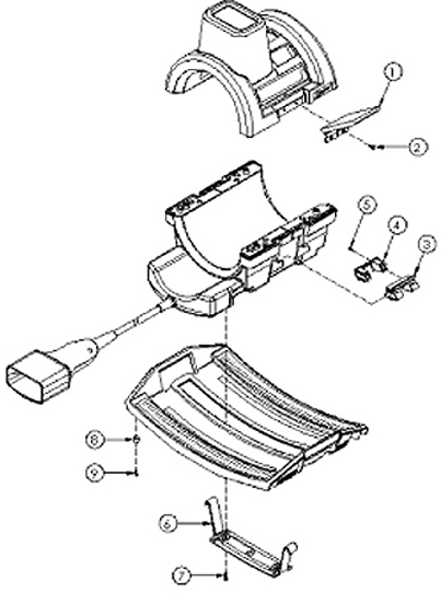
Spare parts are listed below.
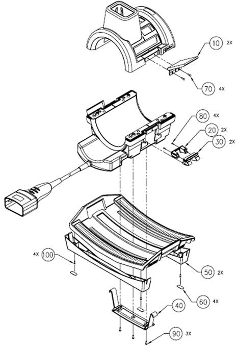
The item numbers in the table refer to the spare part repair kit diagrams below.
| Item | Description | Supplier Part | Qty |
| 1 | Draw Latch | 20074P2 | 2 |
| 2 | #6-32 x 0.438 FHMS, Brass | 20117P25 | 4 |
| 3 | Handle, Coil Lock | 19711P1 | 2 |
| 4 | Cover, Lock Handle | 19712P1 | 2 |
| 5 | #4-40 x 0.375 PHMS, Brass | 20136P2 | 4 |
| 6 | T-Bracket | 19713P1 | 1 |
| 7 | #10-32 x 0.375 PHMS, Brass | 20136P14 | 3 |
| 8 | Rubber Bumper | 19727 | 4 |
| 9 | #6-32 x 0.50 PHMS, Brass | 20136P6 | 4 |
| Item | Quantity | Description | Supplier Part Number |
| 10 | 2 | Draw Latch | 4535-301-8418* |
| 20 | 2 | Handle, Coil Lock | 4535-301-8076* |
| 30 | 2 | Cover, Lock Handle | 4535-301-8077* |
| 40 | 1 | T-Bracket | 4535-301-8078* |
| 50 | 2 | Flat Table Foot | 4535-302-9815* |
| 60 | 4 | Non-Skid Pads | 4535-302-5665* |
| 70 | 4 | No. 6-32 x 0.438 FHMS, Brass Screws | 4535-301-8603* |
| 80 | 4 | No. 4-40 x 0.375 PHMS, Brass Screws | 4535-301-8643* |
| 90 | 3 | No. 10-32 x 0.375 PHMS, Brass Screws | 4535-301-8637* |
| 100 | 4 | No. 6-32 x 0.50 PHMS, Brass Screws | 4535-301-8658* |
| * The revision number appears as the last digit of the part number and replaces the asterisk (*). | |||
Tools and Test Equipment
(For cable replacement) 1 flat-head screwdriver for #6 size screws
(For mechanical components) 1 flat-head screwdriver for #4, 6, and 10 size screws
(For testing cable functionality) Digital multimeter
(For mechanical components) Loctite 222 (12-month shelf life), part 46-170683P1 (one 10 cc bottle)
Cable Check and Replacement
| Notice | |
|---|---|
Cable Continuity Check
-
Select the OHMMETER function on the digital multimeter (DMM).
Figure 5. HD System Connector (View from Cable End) 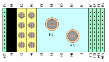
-
Using the DMM, verify continuity of the cable by performing the following operations on the system connector:
-
Continuity check from A1 to A2 pins
-
Continuity check from M9 to M10 pins
-
-
Remove six brass screws from the underside of the cable connect housing, and unplug the cable from PCB.
-
Access the reference points on the exposed interconnect PCB.
Perform continuity checks on the following reference points from the interconnect PCB to the system connector block.
From To MC-1 C1 REF LOAD H3 TX F2 PA +10 VDC M3 MC BIAS J1 COIL ID M7 COIL ID RTN M8 -
Flex the cable while checking to test for intermittent open and short conditions in the cable.
-
If the cable fails any of the tests, replace the cable assembly by contacting GE Customer Service.
-
If the cable passes the tests, plug the interconnect PCB back into the preamp PCB and replace underside with the six brass screws.
-
Cable Replacement Procedure
-
Remove the bottom screws of the extended housing.
-
Carefully remove the top cover and place to the side.
-
Unseat the cable from the cradle and carefully remove the small PCB with 20-pin connector from the large PCB.
-
Set the cable assembly aside.
-
Replace it with the new cable assembly, fully mating the 20-pin connector and socket.
-
Seat the cable assembly into the cradle, and replace the cover.
-
Ensure that the cable end sits level and upright.
-
Hand tighten the screws, and scan the coil to ensure proper assembly.
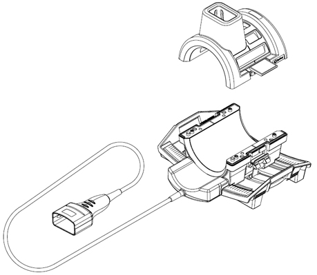
Figure 6. Cable Replacement 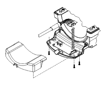
Mechanical Parts Replacement
Mechanical Hardware Check
-
Lift the coil locks on both sides of the coil, and slide the coil from side to side.
The coil must slide freely back and forth on the base with no binding or grinding.
-
Lock the coil in the center of the base. Check the bottom of the base to ensure the four rubber feet are tight.
-
Make sure that the coil latch is secure and that the base lock is fastened.
Draw Latch Replacement
-
Remove #6-32 x 0.438 FHMS brass screws, quantity 2 (item #2) from the housing and replace the old draw latch with the new draw latch.
-
Use Loctite 222 on the brass screws. Insert them into the draw latch and hand tighten.
-
Hand tighten the brass screws.
-
Test the draw latch to ensure proper assembly.
Handle and Cover: Coil Lock Replacement
-
Mate the new handle and cover pieces together, and fasten with #4-40 x 0.375 PHMS brass screws.
-
With both handle locks in the upright position, pry one side of the handle lock from the cradle on the side of the housing.
-
Use Loctite 222 on the brass screws. Replace the lock assembly with the new one, and secure with the screws.
-
Slide the old lock assembly from the T-bracket (item #6) and replace it with the new lock assembly.
-
Place one end of the lock assembly into the cradle of the housing and maneuver the other side into the cradle.
-
Test the lock mechanism to ensure proper assembly.
T-Bracket Replacement
-
Remove the coil lock as instructed in Handle and Cover: Coil Lock Replacement and replace the T-bracket.
-
Replace the coil lock assembly as instructed in Handle and Cover: Coil Lock Replacement.
-
Test the lock mechanism to ensure proper assembly.
Rubber Bumper Replacement
-
Remove #6-32 x 0.50 PHMS brass screw (item #9).
-
Replace the rubber bumper and tighten the brass screw.
-
Use Loctite 222 on the PHMS screws, replace the baseplate rail with the new one, and secure with the screws.
-
Cover the #6 PHMS screws with the new skid pads from the kit.