
- Discovery MR750w and SIGNA™ Architect T 3.0T System Service Methods
- 5690002-2EN Revision 4
- 00000018WIA308CCE20GYZ
- id_131063882.0
- Feb 22, 2021 1:46:52 AM
3.0T HD 3-Channel Shoulder Coil FRUs and Cable Replacement
Personnel Requirements
| Required Persons | Procedure Timing |
| 1 | 30 minutes |
Overview
This document contains the FRU list and instructions to replace the cable assembly on the 3.0T HD 3-channel shoulder coil by GE/USAI, catalog M3335LR (A-port system) and M7001KE (P-port system).
FRUs
| Description | GEHC Part # |
| Shoulder coil |
2416878 5498924 (R) |
| Cable assembly (A-port) | 2416877 |
| Cable assembly (P-port) | 5554682 |
| Phantom positioner | 2375136-3 |
| Patient pad | 2375136-5 |
| FRU, SPACER PAD, SHOULDER | 2413827 |
| Kit, Vinyl and Foam Repair | 5440960 |
| Strap and Pin FRU, Shoulder Coil | 5370109 |
Tools and Test Equipment
Standard tool set
Item: ESD kit with monitor (wrist strap, 10 feet) or equivalent
Qty: 1
Part#: 2220483
Cable Replacement
Remove Cable from Coil
-
Remove the coil from the magnet room before you begin this procedure.
-
Wear an ESD wrist strap to avoid electrostatic discharge.
-
Remove the screws that attach the covers to the unit.
-
Remove the covers.
Figure 1. Covers and Screws 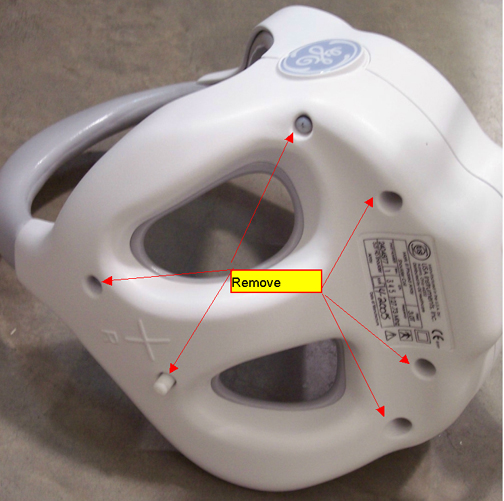
-
Disconnect the RF cables and the DC wires from the feed boards.
Figure 2. Disconnect RF Cables 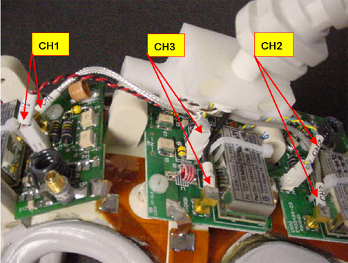
-
Remove the two screws from the strain relief clamp.
Figure 3. Strain Relief Clamp 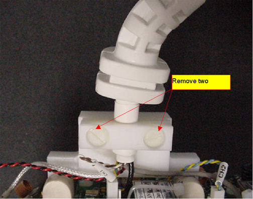
-
Remove the cable from the coil.
Install New Cable in Coil
(For RRx receive chain systems) Both the A-port and P-port cable assemblies are compatible with the RRx receive chain. You can use either assembly to complete this procedure.
-
Attach the cable to the coil with the cable clamp.
Figure 4. Cable with Cable Clamp to Coil 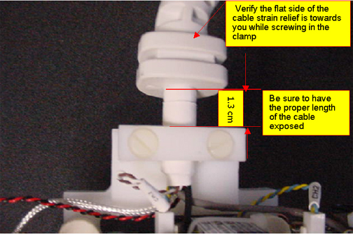
-
Connect the DC wires and RF cables Figure 2.
Table 2. Connections RF Wires Color Label Black CH3 Gray CH2 Silver CH1 DC Wires Color Label Blue, yellow (twisted) CH2 Red, black (twisted) CH1 Brown, white (twisted) CH3 -
Replace the covers and screws Figure 1.
Finalization
Before returning the coil to the customer, perform 3.0T HD 3–Channel Shoulder Coil Setup for MCQA Test.