- id_12374740
- Version: 1.2
- Date: Jul 5, 2019 10:03:32 PM
In-Room Display Fiber Optic Converter Box Replacement
Prerequisites
| Required persons | Preliminary requirements | Procedure | Finalization |
|---|---|---|---|
| 1 | Not Applicable | 45 minutes | 30 minutes |
| Item | Quantity | Effectivity | Part number | Manufacturer |
|---|---|---|---|---|
| Standard Screwdriver | 1 | - | - | - |
| Phillips Screwdriver | 1 | - | - | - |
| Pliers | 1 | - | - | - |
| Allen Wrench Set | 1 | - | - | - |
| Item | Quantity | Effectivity | Part number | Manufacturer |
|---|---|---|---|---|
| Fiber Optic Converter Box, OR | - | - | - | - |
| Converter Box with IRD, Black, OR | - | - | - | - |
| Converter Box with IRD, White | - | - | - | - |
|


| Condition | Reference | Effectivity |
|---|---|---|
|
Host computer and GOCAA must be powered off as described below. |
- | - |
Powering Off Host and GOCAA
Shut Down Software
Procedure
- Shut down any system applications that are still running.
- Click Tools.
- On the Service Desktop, click System Shutdown.
- Confirm shutdown by clicking OK.
Wait for the system to indicate on the monitor that it is safe to power off the computer before proceeding. It usually takes about 90 seconds for this message to display. Monitor the screen and wait until the light turns yellow.
Remove Power to Operator Workstation
Procedure
- Verify that the power indicator on the Operator Workstation is off.
- The host circuit breaker is located on the front of the PDU.
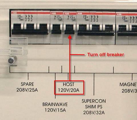
Set the host circuit breaker to the DOWN position to disconnect power.
Figure 1. Location of PDU Host/PC Breakers
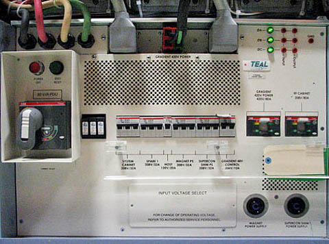
Figure 2. Host Breaker
- Apply LOTO (see LOTO for the PGR PDU/Gradient Subsystem).
Removing GOC Covers and AC Power Cord
Procedure
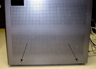
- note:Remove the screws that secure the left and right side panels of the GOC.
Take extra precaution if the site has installed the optional GOC UPS accessory.
Figure 3. GOC Left Panel
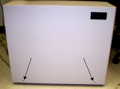
Figure 4. GOC Right Panel
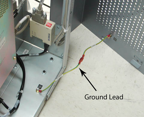
- Disconnect the ground leads from both side panels.
Figure 5. Left Side Panel Ground Lead
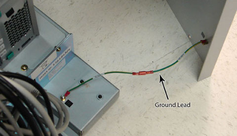
Figure 6. Right Side Panel Ground Lead
- Remove both GOC side panels and set aside.
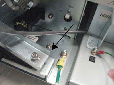
- Remove the strain relief plate from the input AC power cable.
Figure 7. Strain Relief Plate
- Unplug the AC input cable from the GOC power distribution supply inlet connector.
Replacing Fiber Optic Converter Box
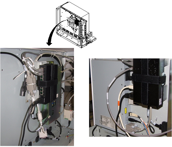
Refer to Figure 8 for the box connector assignments and Figure 9 for box/cable harness location in GOC.
Remove Converter Box
Procedure
- Disconnect run E3019 from J4 and the sensor cable from J5.
- Disconnect the USB cable from J1.
- Disconnect the fiber optic cable run P2026 from J3.
- Disconnect the DVI-D cable from J2.
- Disconnect the AC power cord from the fiber optic converter box.
- Remove the fiber optic converter box by loosening the four M5
screws using the Phillips driver, and then remove the box.
Figure 8. Fiber Optic Converter Box Connections and Power
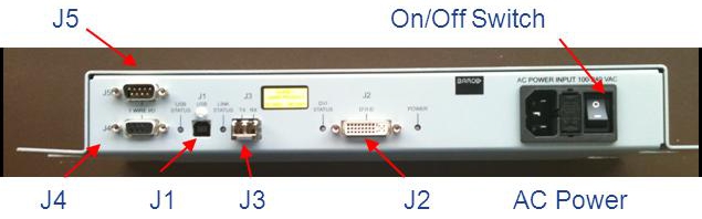
Figure 9. Mounting Location of Fiber Optic Converter Box in GOC
Replace Converter Box
Procedure
- With the four M5 screws loose in their mounting holes, install the fiber optic converter box, and then secure the four M5 mounting screws using the Phillips driver.
- Connect the AC power cord to the fiber optic converter box and set the power switch to ON. The device will not power up until the operator console power is turned back on at the end of this procedure.
- Connect the DVI-D cable to J2.
- Connect the fiber optic cable run P2026 to J3.
- Connect the USB cable to J1.
- Connect run E3019 to J4 and the sensor cable to J5.
Installing AC Power Cord and GOC Covers
Install AC Power Cord
Procedure
- Mate the AC input cable to the inlet connector on GOC power distribution supply.
- Install the strain relief plate (see Figure 7) and secure it to hold the input AC power cable in place
Install GOC Side Cover
Finalization
Procedure
- Remove LOTO from the PGR/PDU host breaker and set the host breaker on the PDU to ON.
- Reboot the host computer.
- On the Common Service Desktop, select Diagnostics > Hardware > Magnet Room > In Room Display.
- Run the In Room Display diagnostic.