- id_12373866
- Version: 1.12
- Date: Dec 2, 2019 3:46:57 PM
HP Z420 Lower Level FRU Replacement
Prerequisites
| Required persons | Preliminary requirements | Procedure | Finalization |
|---|---|---|---|
| 1 | - | As required | 30 minutes |
| Item | Quantity | Effectivity | Part number | Manufacturer |
|---|---|---|---|---|
| Standard FE Toolkit | 1 | - | - | - |
| 4 mm Hex Key Wrench | 1 | - | - | - |
| ESD Mat and Wrist Strap | 1 | - | - | - |
| Item | Quantity | Effectivity | Part number | Manufacturer |
|---|---|---|---|---|
| Hard drive | 3 | hard drive replacement |
See FRU manual. |
- |
| DVD drive | 1 | DVD drive replacement |
See FRU manual. |
- |
| Battery, Type 2032 Coin, 3 V, Lithium | 1 | battery replacement |
See FRU manual. |
- |
| Condition | Reference | Effectivity |
|---|---|---|
|
Access to both the front and rear of the operator console is required. Move the console away from walls and remove obstacles in room. |
- | - |
Overview
This procedure describes the steps to replace lower level FRUs in the HP Z420 host PC, including:
-
DVD drive
-
Hard drive
-
CMOS battery
Workstation Service Preparation
Procedure
- (For hard drive replacement) Ask the customer to archive all images to an external storage device such as a PACS or DVDs.
- Perform SaveInfo.
- Close any PC applications and power down the GOC.
The GOC supports an optional UPS. Confirm the site’s configuration.
- Perform LOTO on the GOC and operator workspace. See the latest
revision of the MR Service Safety Manual, PN 5452735,
available from the online documentation library.
For added protection, disconnect the twist-n-lock or modular plug main power cable from the rear of the console.
- Remove the two screws on the left side panel of the GOC.
- notice
- Remove the left side panel of the GOC by lifting it up.
- Disconnect the short ground lead that connects the side panel to the GOC main chassis at the center of the lead.
 caution
- Remove all the cables connected to the computer, ensure they are properly labeled, and note their locations for reattachment.
- caution
- Remove the host computer from the GOC.
Figure 1. Removing Computer from Brackets
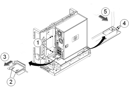
Item Description 1 Remove the two screws securing the back bracket to the GOC. 2 Loosen the two screws on the back slide plate. 3 Slide the plate backward. 4 Loosen the two screws on the side slide plate. 5 Slide the plate in the direction of the arrow. - Carefully remove the computer using the back and bottom brackets.
- notice
- notice
- Remove the two screws that secure the left side panel to the rear of the PC.
- Remove the left side panel of the PC by pulling the latch out, and sliding the cover back. Set the cover aside in a safe location.
 |
 |
|
|
DVD Drive Replacement
Procedure
- To prevent damage, do not remove the DVD drive from its antistatic packaging until you are ready to install it.
- Remove the front panel on the computer by gently unsnapping
the plastic locks located on the left side and pulling on the left
side of the cover.
- Pull the cover out just far enough to disengage the locks. If you pull them out too far, you can damage the locks on the right side of the cover.
- Push the cover slightly to the right as you pull out on the cover.
- Set the front cover aside in a safe location.
Figure 2. Remove Front Panel
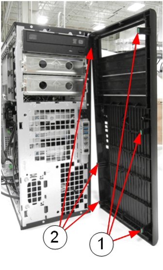
Item Description 1 Release plastic locks 2 Plastic hinges (breakable) - Locate and unplug the power/data cable harness (D4) on the back
of the DVD drive.
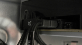
Figure 3. Power/Data Cable Harness (D4) on Rear of DVD Drive
- Pull out the plastic lock located on the left side of the PC
and carefully slide out the DVD drive.
Figure 4. Remove DVD Drive
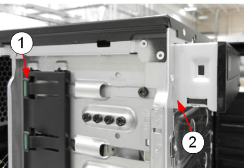
Item Description 1 Plastic lock 2 DVD drive being removed - Remove the guide screws from the old DVD drive and install them on the new unit.
- Install the new DVD drive by pulling out on the plastic lock and sliding the new drive into the open slot until it is securely seated.
- Reconnect the power/data cable harness to the new DVD drive.
- Reinstall the front panel on the PC.
- If you are finished replacing FRUs, proceed to Reinstalling Host Computer in GOC.
Hard Drive Replacement
The HP Z420 has three hard drives.
Figure 5. Hard Drives in HP Z420
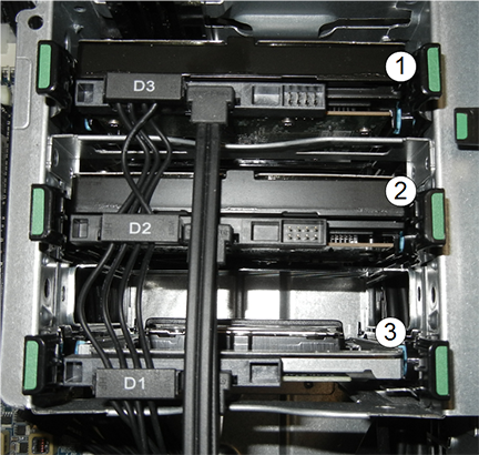
| Item | Description |
| 1 | Top slot, power connection D3 |
| 2 | Middle slot, power connection D2 |
| 3 | Bottom slot, power connection D1 |
Procedure
- To prevent damage, do not remove the hard drive from its antistatic packaging until you are ready to install it.
- Lay the computer on its side to allow for better access.
- Remove the power/data cable harness from the hard drive.
- Press gently in on the two green tabs on either side of the hard drive and slide the hard drive carrier out of the slot.
- Press gently in on the two back tabs of the hard drive carrier and remove it from the slot carrier.
- caution
- Remove the drive from the carrier by twisting the carrier slightly
to disengage the 4 pins holding the hard drive into the carrier.
Figure 6. Hard Drive and Carrier
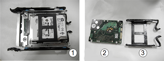
Item Description 1 Hard drive in slot carrier 2 Hard drive 3 Carrier - Remove the new hard drive from its antistatic packaging.
- Install the new hard drive into the hard drive carrier. Carefully
line up the pins and secure the drive.
Avoid touching the circuitry on the bottom of the hard drive.
- Slide the hard drive carrier into the slot carrier until it is firmly seated.
- Insert the slot carrier into the drive slot.
- Attach the power/data cable harness.
- Confirm the data cables from all three hard drives are connected
to the correct SAS device locations.
Drive Slot Power Data Contents Top HDD3 SAS2 Image data Middle HDD2 SAS1 Image data Bottom HDD1 SAS0 Application software - If you are finished replacing FRUs, proceed to Reinstalling Host Computer in GOC.
|
CMOS Battery Replacement
Procedure
- Lay the workstation on its side with the system board facing up.
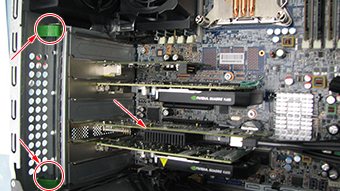
- Press on the green tabs of the card in slot 4 and remove the
card.
Figure 7. Slot 4 Card Removal
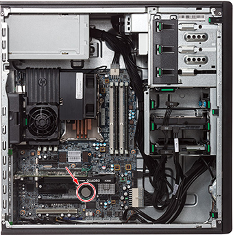
- Locate the CMOS battery on the HP computer system board.
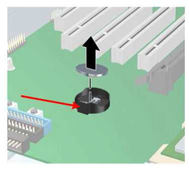
Figure 8. CMOS Battery Location
- Remove the old CMOS battery. Release the CMOS battery from its
holder by pulling back on the spring clip. Do NOT put pressure on
the holder.note:
Two small screwdrivers may be needed – one to push the battery out of the grip, the other to lift the battery up.
Figure 9. CMOS Battery Removal
- Let the computer sit for at least 3 minutes to allow the CMOS memory to clear.
- Install the new battery. Make sure the spring clip snaps over the battery, holding it in place. The battery’s positive (+) side should be facing upward.
- Locate, press and hold the CMOS Reset button for five seconds.
- At power-up, make sure to update settings as described in Step 3.
Reinstalling Host Computer in GOC
Procedure
- Replace the left side panel of the PC and secure it with the two screws removed earlier.
- Return the Z420 host computer to the GOC and replace and secure all cables and covers.
-
(For CMOS battery replacement) Obtain the GE
Equipment Maintenance sticker (part number 5661793) and write the
date on the sticker and place the sticker on the GOC for future reference.note:
Place the sticker on either side of the GOC, where it can be easily viewed.
Powering on Operator Console
Procedure
- Remove LOTO.
- Power ON the GOC at the rear of the GOC and then power up the host PC.
-
IF THE CMOS BATTERY WAS REPLACED, press F10 as soon as the hp invent screen
appears. Setup displays at the lower right of
the screen. Perform the following steps:
- note:At the language prompt, leave the setting on English or use the arrows to select the language. Press Enter to confirm.
A message might appear, indicating that system options are not set. Press F1 to continue.
- Under File, select Set Time and Date and enter the proper time. Use the Tab key to move the cursor and use the left and right arrow keys to change values.
- Restore customized BIOS settings. Leave all HP defaults except
for the following:
Table 5 HP Z420 BIOS Changes Advanced VGA Configuration Slot 5: Nvidia VGA controller Primary VGA device Slot 2: Nvidia VGA controller Non-boot device - At the File menu, use the down arrow to highlight Save Changes and Exit and press Enter.
- The following message is displayed: Are you sure you want to Save Changes and Exit?
- Be sure to press yes to save the settings. The system reboots. BIOS configuration is complete.
Finalization
Procedure
- Select from the following table the appropriate actions for
Finalization, then proceed to Step 2.
FRU Item Replaced Actions to be performed DVD drive Reboot and confirm DVD and Read/Write images. Hard drive Reload software. CMOS battery -
Shut down PC and turn off power
-
Re-apply power and restart PC
-
Verify date/time is correct (CMOS battery is properly retaining date/time)
-
- Reboot and ensure that no memory BIOS errors appear during the boot process.
- Run a goodbye scan (check scan)
- Verify that all customer functions are operational (auto voice, filming, network, archive).
- Reinstall the console front and rear covers.
- (For DV25 software or later) Computer hardware replacement may cause a change in the 16-character service license ID code. Renew any site license softkeys that were affected by the hardware replacement.