- id_12373700
- Version: 1.9
- Date: Jul 5, 2019 6:08:29 PM
HP 8400 Lower Level FRU Replacement
Prerequisites
| Required persons | Preliminary requirements | Procedure | Finalization |
|---|---|---|---|
| 1 | Not Applicable | As required minutes | 30 minutes |
| Item | Quantity | Effectivity | Part number | Manufacturer |
|---|---|---|---|---|
| Standard FE Toolkit | 1 | - | - | - |
| ESD Mat and Wrist Strap | 1 | - | - | - |
| Maintenance label | 1 | - | - | - |
| Item | Quantity | Effectivity | Part number | Manufacturer |
|---|---|---|---|---|
| Single 1 GB FBD DDR2-667 Registered ECC memory module | 4 | Memory module replacement |
See FRU manual |
- |
| Single 2 GB FBD DDR2-667 Registered ECC memory module | 4 | Memory module replacement |
See FRU manual |
- |
| Battery, Type 2032 Coin, 3 V, Lithium | 1 | CMOS battery replacement |
See FRU manual |
- |
| Run #1064 SCSI Tower Cable | 1 | SCSI card replacement |
See FRU manual |
- |
| Adaptec U320 Dual Port SCSI Card | 1 | SCSI card replacement |
See FRU manual |
- |
| Hard disk drive | 1 | Hard disk drive replacement |
See FRU manual |
- |
| DVD drive | 1 | DVD drive replacement |
See FRU manual |
- |
Overview
Use this procedure to replace the following lower level FRUs in a HP 8400 host PC:
-
Memory modules
-
CMOS battery
-
SCSI card
-
Hard disk drive
-
DVD drive
Workstation Service Preparation
Procedure
- Close any PC applications, and power down the GOC.
- Perform LOTO on the GOC/operator workspace. See the latest revision of the MR Service Safety Manual, PN 5452735, available from the online documentation library.
- Remove the two screws on the left side panel of the GOC.
- notice
- Remove the left side panel of the GOC by lifting it up.
- Disconnect the short ground lead that connects the side panel to the GOC main chassis at the center of the lead.
- notice
- notice
- Remove all the cables connected to the computer, ensure they are properly labeled, and note their locations for reattachment.
- Remove the HP 8400 from the GOC.
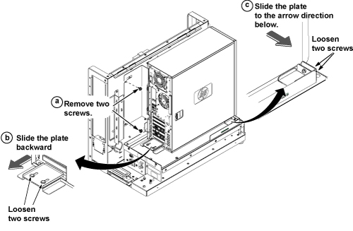
- Remove the two screws securing the back bracket.
- Loosen the two screws on the back slide plate, and slide the plate backward.
- Loosen the two screws on the side slide plate, and slide the
plate in the direction of the arrow.
Figure 1. Removing HP 8400 Computer from GOC
 caution
- Carefully remove the computer using the back and bottom brackets from the GOC.

- notice
- notice
- Remove the two screws that secure the left side panel to the rear of the PC.
- Remove the left side panel of the PC by pulling the latch out, and sliding the cover back. Set the cover aside in a safe location.
- Lay the workstation on its side with the system board facing up.
 |
|
|
Replacing Memory Module
The fan assembly must be removed only when replacing the memory modules.
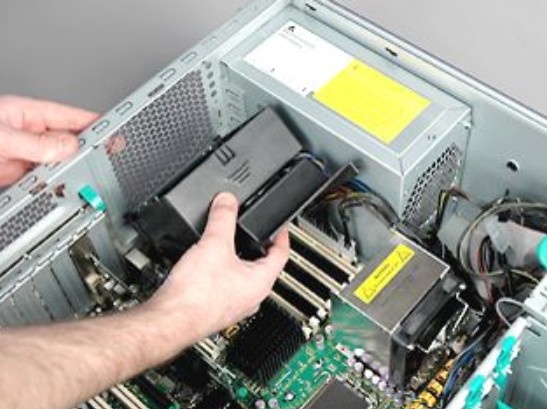
Removing Fan Assembly
Procedure
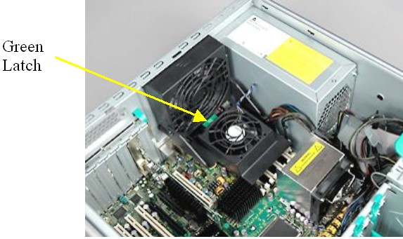
- Press down on the green release latch at the bottom of the system/memory
fan assembly, and rotate the memory fan holder up until it snaps into
a vertical position.
Figure 2. System/Memory Fan Assembly Latch
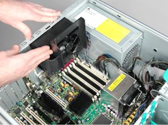
- Disconnect the system and memory fan cables from the system board.
- Press down on the top of the system/memory fan assembly to release
the retaining latch.
Figure 3. Removing Retaining Latch on Assembly
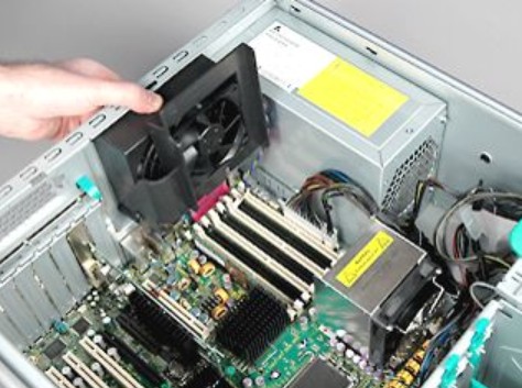
- Rotate the assembly inward until the hinge tabs on the bottom of the assembly are released.
- Lift and remove the system/memory fan assembly from the chassis.
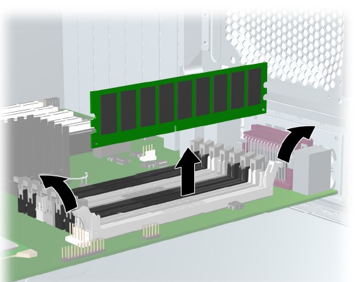
Removing Memory Module
Procedure
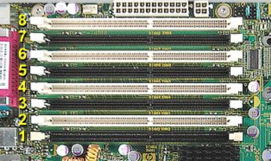
- Gently push out and down on the socket levers on each side of
the slot that contains the suspected faulty memory module.
Figure 4. Socket Levers on Slot Locations
- Lift the memory module straight up and remove it from the unit.
Figure 5. Removing Memory Module
Installing Memory Module
When installing a memory module, be aware that memory modules must be loaded in valid configurations. Refer to the FRU manual for valid configurations.
Procedure
- Ensure that the socket levers are still out and away from the memory slot.
- notice
- Place the new memory module into the slot, and push down firmly until the memory socket levers snap into place.
- Ensure that the module is fully inserted and properly seated in the slot.
|
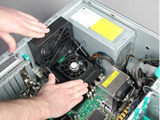
Installing Fan Assembly
Procedure
- Insert the hinge tabs on the bottom of the system/memory fan
assembly into the slot on the chassis.
Figure 6. Inserting System/Memory Module Fan Assembly
- Rotate the top of the assembly up until the retaining latch
snaps into the slot on the chassis.
Figure 7. Latched System/Memory Module Fan Assembly
- Reconnect the system and memory fan cables to the system board.
- Rotate the system/memory fan assembly holder down until it snaps
into a horizontal position.
Figure 8. Horizontal Position for System/Memory Module Fan
- Proceed to Reinstalling Host Computer in GOC.
Replacing CMOS Battery
Procedure
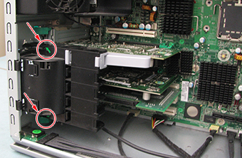
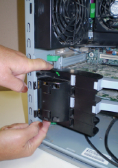
- Remove the video card as follows:
- Press on the green arrows on the securing block for the video
board and remove the securing block.
Figure 9. Video Card Securing Block Removal
- Press on the green tab of the video card and gently pull out
the video card.
Figure 10. Video Card Removal
- Press on the green arrows on the securing block for the video
board and remove the securing block.
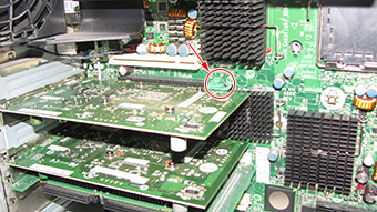
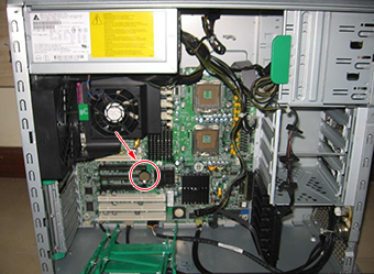
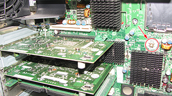
- Locate the CMOS battery on the HP computer system board.
Figure 11. HP 8400 CMOS Battery Location
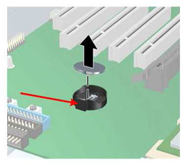
- Remove the old CMOS battery. Release the CMOS battery from its
holder by pulling back on the spring clip.
Figure 12. CMOS Battery Removal
- Let the computer sit for at least 3 minutes to allow the CMOS memory to clear.
- Install the new battery. Make sure the spring clip snaps over the battery, holding it in place. The battery’s positive (+) side should be facing upward.
- Reinstall the video card and the video board securing block.
- Make sure to perform Step 3.
Replacing SCSI Card
Procedure
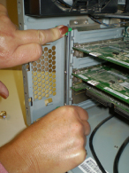
- Locate the two black tabs on the top and bottom of the spring-loaded card retainer.
- While depressing both tabs, remove the retainer.
Figure 13. Black Tabs on Card Retainer
- Depress the two green tabs on the inside of the PC to release
the locking mechanism holding the boards in place.
Figure 14. Locking Mechanism on Card Retainer
- Remove the SCSI card from the fifth slot from the top.
- Install the new SCSI card firmly into the fifth slot from the top.
- Restore the locking mechanism holding the boards in place by pulling back the two green tabs on the inside of the PC.
- Restore the spring-loaded card retainer.
- Connect the SCSI tower cable to the left port of the SCSI card, and route the other end of the cable to the back of the SCSI tower.
- Proceed to Reinstalling Host Computer in GOC.
Replacing Hard Disk Drive
Because of the way the hard disk drives are partitioned, if one of the hard disk drives becomes corrupted and has no read/write capabilities, information saved on the system (since the most recent archive) will be lost. Use the HP Diagnostics Tool CD to identify the defective hard drive.
Procedure
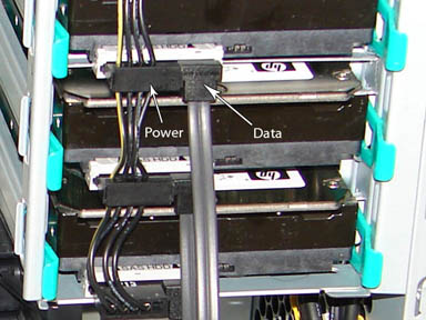
- Remove the power cable and the data cable from the defective
hard disk drive.
Figure 15. Removing Power and Data Cables
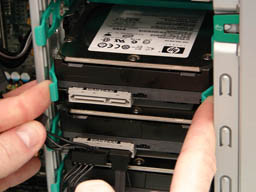
- Remove the defective drive by pinching the green restraining
tabs together, then slowly pulling the drive out.
Figure 16. Restraining Tabs on Disk Drive
- Confirm that the data cables from all three drives are connected
to the correct SAS device locations.
Figure 17. SAS Device Locations
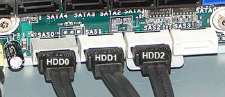
Table 4 Hard Disk Drive Connections Drive Slot Drive ID SAS ID Top HDD2 SAS2 Middle HDD1 SAS1 Bottom HDD0 SAS0 - Install the replacement hard drive by reversing the previous steps.
- Perform disk wipe procedure. See the Disk Management Tool Service Manual, PN 5500610-1EN, available from the online documentation library.
- Reinstall the left side panel and proceed to Reinstalling Host Computer in GOC.
Replacing DVD Drive
Procedure
- notice
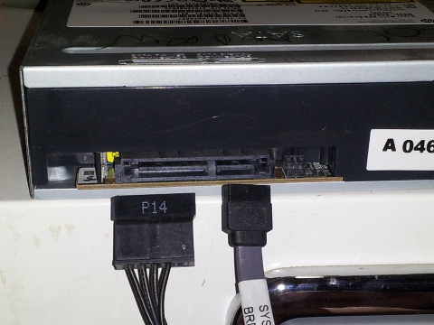
- Disconnect the power, drive, and audio cables from the drive.
Figure 18. Location of Power and Data Cables (EIDE DVD Drive)
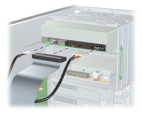
Figure 19. Location of Power and Data Cabes (SATA DVD Drive)
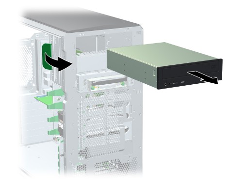
- Lift the green drive release lever and slide the drive out of
the chassis.
Figure 20. DVD Drive Removal
- Install the new DVD drive by pulling out on the plastic lock while sliding the new drive into place in the open slot.
- Connect the power and data cables to the new DVD drive as shown in either Figure 18 or Figure 19 based on the DVD drive connection type.
- Proceed to Reinstalling Host Computer in GOC.
|
Reinstalling Host Computer in GOC
Procedure
- Replace the left side panel of the PC and secure it with the two screws removed earlier.
- Return the HP 8400 host computer to the GOC and replace and secure all cables and covers.
-
(For CMOS battery replacement) Obtain the GE
Equipment Maintenance sticker and write the date on the sticker and
place the sticker on the GOC for future reference.note:
Place the sticker on either side of the GOC, where it can be easily viewed.
Powering on Operator Console
Procedure
- Remove LOTO from the GOC/operator workspace.
- Power ON the GOC at the rear of the GOC and then power up the host PC.
-
If the CMOS battery was replaced:
- If the CMOS battery was replaced, and the PC will not turn on,
press and hold the CMOS Reset button for five seconds.
Figure 21. CMOS Reset Button
- At the language prompt, leave the setting on English or use the arrows to select the language. Press Enter to confirm.
- Set the time and date. Use the Tab key and the up/down arrow keys to move the cursor and use the left and right arrow keys to change values. Press F10 to save the changes.
- Restore customized BIOS settings. Use the up/down and left/right
arrow keys to navigate the menus. Leave all HP defaults except the
following:
Table 5 HP 8400 BIOS Changes Location Parameter Value Storage / Storage Options SATA Emulation Separate IDE Controller, then F10 Security / Network Service Boot Network Service Boot Disable, then F10 Power / OS Power management ACPI S3 Support Disable, then F10 Advanced / Power On options After Power Loss ON, then F10 Advanced / Device Options S5 Wake On LAN Disable, then F10 Advanced / Device Options NIC PXE Option ROM Disable, then F10 Advanced / Slot 1 – PCI Slot 1 Option ROM Download Disable, then F10 Advanced / Slot 2 PCIe Slot 2 Option ROM Download Disable, then F10 Advanced / Slot 3 – PCIe Slot 3 Option ROM Download Disable, then F10 Advanced / Slot 4 – PCIe Slot 4 Option ROM Download Disable, then F10 Advanced / Slot 5 – PCI-x Slot 5 Option ROM Download Disable, then F10 Advanced / Slot 6 – PCI-x Slot 6 Option ROM Download Disable, then F10 Advanced / Slot 7 – PCI-x Slot 7 Option ROM Download Disable, then F10 - At the File menu, use the down arrow to highlight Save Changes and Exit and press Enter.
- Press F10 to save the settings.
- If the CMOS battery was replaced, and the PC will not turn on,
press and hold the CMOS Reset button for five seconds.
-
If the DVD drive was replaced: You must
set up the software configuration at either the root or system level
after power up. To set up the software configuration at the system
level, proceed to Step 5. To set up the software configuration at the
root level, proceed as follows:
- After powering up, log in as root with
the password operator.note:
It is possible that the customer changed the default password. If you cannot log in, contact the customer for the correct password.
- Proceed to Guided Install.
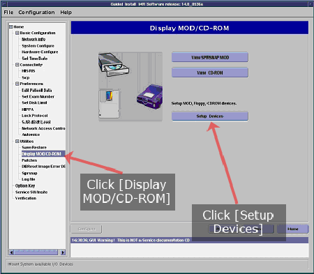
Figure 22. Display MOD/CD-ROM Screen
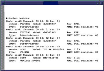
- Open a command window and run the command scsistat.
Figure 23. SCSISTAT Command Reply
- Select Setup Devices.
- When this process is completed, exit Guided Install and log out of root.
- Log in to the system and proceed to Step 5.
- After powering up, log in as root with
the password operator.
-
If the DVD drive was replaced: To set
up the DVD drive software configuration at the system level (if you
opted not to set this up at the root level in Step 4), proceed
as follows:
- After power up, log in as sdc with the
password adw2.0.note:
It is possible that the customer changed the default password. If you cannot log in, contact the customer for the correct password.
- Open a command window.
- Run the command scsistat.
The information below will display. If the information does not display, recheck the power connection, cable connections, and jumper settings, then rerun the scsistat command.
Figure 24. SCSISTAT Command Reply
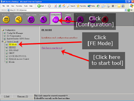
- Launch the MR Service Desktop.
- On the Configuration tab, expand Guided Install, select FE mode and Click here to start the tool.
Figure 25. FE Mode
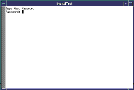
- When the login screen displays, log in as root with the password operator.note:
It is possible that the customer changed the default password. If you cannot log in, contact the customer for the correct password.
Figure 26. Login Screen
- From the Utilities heading in the left navigation
tree, select Display MOD/CD-ROM.
Figure 27. Display MOD/CD-ROM Screen
- Select Setup Devices.
- Proceed to Step 5.
- After power up, log in as sdc with the
password adw2.0.
Finalization
Procedure
- Reboot and ensure that no memory BIOS errors are observed during this process.
- Verify that all customer functions are operational (auto voice, filming, network, archive).
- (For SCSI card replacement, hard disk replacement) Perform the applicable Loading Host System Software procedure to load software and applications onto the operating system.
- Perform a check scan to ensure that the system is operating properly.
- (For DVD drive replacement) Insert media into the new DVD drive and verify proper operation of the drive.
- (For DV25 software or later) Computer hardware replacement may cause a change in the 16-character service license ID code. Renew any site license softkeys that were affected by the hardware replacement.