- id_15667649
- Version: 2.6
- Date: Dec 19, 2019 10:58:38 AM
Dell T5810 Lower Level FRU Replacement
Prerequisites
| Personnel requirements | |||
|---|---|---|---|
| Required persons | Preliminary requirements | Procedure | Finalization |
| 1 | - | - | 2 hours |
| Tools and test equipment | |||
|---|---|---|---|
| Item | Quantity | Part number | Manufacturer |
| Standard FE toolkit | 1 | - | - |
| ESD mat and wrist strap | 1 | - | - |
| Consumables | |||
|---|---|---|---|
| Item | Quantity | Part number | Manufacturer |
| GE Equipment Maintenance sticker | 1 | See FRU manual | - |
| Replacement parts | |||
|---|---|---|---|
| Item | Quantity | Part number | Manufacturer |
| DVD drive | 1 | See FRU manual | - |
| SSD | 2 | See FRU manual | - |
| Battery, Type 2032 Coin, 3 V, Lithium | 1 | See FRU manual | - |
| Required conditions |
|---|
| Access to both the front and rear of the operator console is required. Move the console away from walls and remove obstacles in the room. |
 |
|

 |
|
|
|
|
- DVD drive
- Solid State Drive (SSD)
- CMOS battery
Preparing the workstation
Procedure
- (For SSD Replacement) Ask the customer to archive all images to an external storage device (PACS, DVDs, and so on).
- Do a SaveInfo.
- Close any PC applications and power down the GOC .
The GOC supports an optional UPS. Confirm your site’s configuration.
- Perform LOTO for the GOC/Operator Workspace. See the MR Service Safety Manual (5452735). For added protection, disconnect the twist-n-lock main power cable from the rear of the console.
- Remove the host PC from the GOC. See Dell T5810 Computer Replacement.
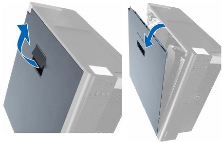
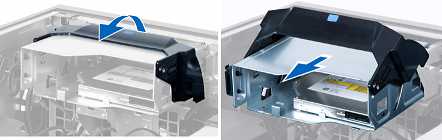
- Lift up the cover release latch and lift the cover upward to a 45-degree angle, and remove it from the host PC.
Figure 1. PC cover removal
Replacing LLFRUs in Dell T5810 host PC
Replacing DVD drive
Procedure
- To prevent damage, do not remove the new DVD drive from its antistatic packaging until you are ready to install it.
- Disconnect the data and power cables from the DVD drive.
Figure 2. Power/cata cable on rear of DVD crive
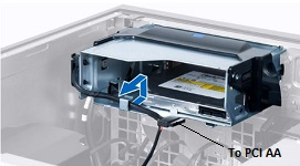
- Disconnect the cable from the GOCAA and unthread the cables from the latches.
Figure 3. Cables Removed from Latches
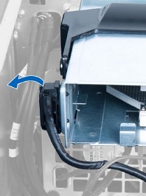
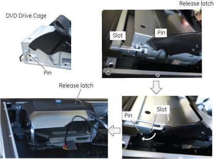
- Press on the clasp to release the latch holding the cables on the side of the cage.
Figure 4. Release latch
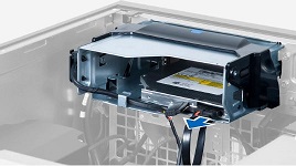
- Lift the release latch on top of the cage, and slide the cage out from the compartment.
Figure 5. DVD drive cage removal
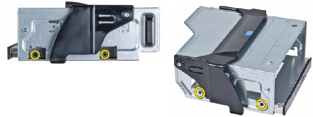
- Remove the four screws that secure the DVD drive to the cage.
Figure 6. Location of screws
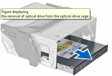
- Remove the DVD drive from the cage.
Figure 7. DVD drive removal
- Install the new DVD drive in reverse sequence, and connect the power and data cables.note: When restoring the DVD Drive cage, lift the release latch and slide the pins on the both side of cage along the slot till they reach to the end. Then, close the release latch.
Figure 8. Tips to restore DVD drive cage
- Continue to Reinstalling host computer in GOC below.
Replacing SSD
Procedure
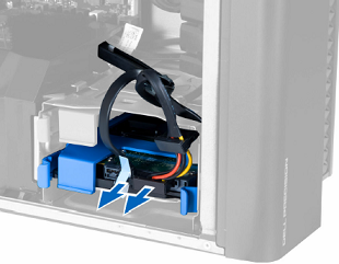
- Disconnect the power supply and data cables from the SSD.
Figure 9. SSD cables removal
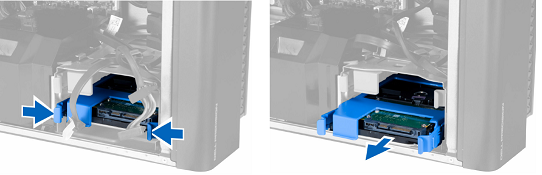
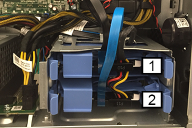
- Press in gently on both sides of the bracket and slide the SSD carrier out of the slot.
Figure 10. SSD carrier removal
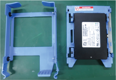
- Remove the bracket from the SSD carrier.
Figure 11. Bracket and carrier
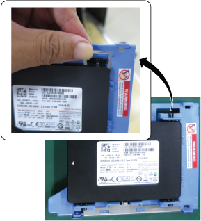
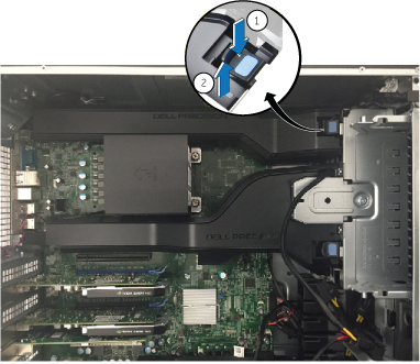
- Press on the two tabs on one side of the SSD carrier to separate the pins from the SSD and remove the SSD from the carrier.
Figure 12. SSD and carrier
 note: You can twist the carrier to separate the pins more easily.Even though the pin is long and the tab is hard, it is possible to detach the pin from the SSD as illustration below.
Figure 13. Pin removal
- Install the new SSD in reverse sequence.There are no jumpers required to configure the disk drives on the Dell T5810. Connect the power cables to the SATA connectors labeled on the board as HDD1 and HDD0.
Figure 14. Hard Drives with wiring harness connections
1 HDD1 - DATA SSD Image data 2 HDD0 - Boot Drive SSD Application software - Perform a disk wipe on all applicable hard drives in the old PC. See the latest revision of the Disk Management Tool Service Manual , PN 5500610-1EN available from the online documentation library.
- Continue to Reinstalling host computer in GOC below.
Replacing CMOS battery
Procedure
- Lay the workstation on its side with the system board facing up.
- Remove the bracket that holds the DVD Drive (refer to Replacing DVD drive),
- Push the tab and lift the long black cover.
Figure 15. Remove long bracket
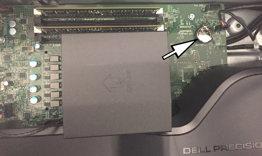
- Find the CMOS battery on the Dell computer system board.
Figure 16. CMOS battery location
- Move the latch away from the battery to remove the battery from the socket.If necessary, you can use a small screwdriver to remove the battery.
- Let the computer sit for a minimum of 3 minutes to let the CMOS memory clear.
- Install the new battery, and push the battery down until the release latch moves back into place and secures it. The battery’s positive (+) side should point up.
- Continue to Reinstalling host computer in GOC below.
Reinstalling host computer in GOC
Procedure
- Recover the left side cover of the host computer.
- Reinstall host computer to the GOC in reverse order of removal.
- Recover the GOC left side cover.
- Confirm that all cable connections to the GOC and host PC are tight.
- Get a GE Equipment Maintenance sticker, and write today’s date on the sticker. Put the sticker on the GOC where it is easily seen.
Finalization
Prerequisites
| FRU Item Replaced | Actions to be performed |
|---|---|
| DVD drive | Reboot and confirm that the DVD drive can read and write images. |
| Hard drive | Reload the software. |
| CMOS battery |
|
Procedure
- Remove LOTO on the GOC to return power. If needed, reconnect the twist-n-lock main power cable to the rear of the console. See the MR Service Safety Manual (5452735).
- Push the power button on the front of the host PC within the GOC .
- note: If you replaced the battery, you need to go to the BIOS settings before the host PC starts. To get into the BIOS menu, you need to push F2 as soon as the Dell circle shows. The Dell circle only shows for 5 seconds.(For CMOS battery replacement) Push F2 when you see the Dell circle on the screen. Do the following steps:
- If you see a message that indicates the time-of-day is not set, press F2 to continue.
- Select Set Time and Date and enter the correct time. Use the Tab key to move the cursor and use the left and right arrow keys to change values.After you set the time and date, the BIOS settings will open.
- Restore the customized BIOS settings. Change only the values shown in the table below:
Table 1 Customized BIOS settings Section Sub-Section Setting General General Boot Sequence Diskette Drive - disabled Diskette Drive - disabled USB Storage Device - disabled Boot Order: ODD, SSD, SSD System Configuration SATA Operation AHCI enabled Memory Map IO Memory Map - enabled Performance Intel SpeedStep Enable Intel SpeedStep - disabled c-States C states - disabled Dell Reliable Memory Technology Enable Dell RMT - disabled Virtualization Support Virtualization Enable Intel Virtualization - disabled VT for Direct IO Enable VT for direct IO - disabled - Click Apply to save changes, and then press Exit.The system reboots. BIOS configuration is complete.
- note: Make sure the host PC front panel power LED is illuminated as a steady blue signal.(For SSD Replacement) Load software and applications onto the operating system.
- Run a goodbye scan.
- Make sure all customer functions are operational (auto voice, filming, network, archive).
- (For DV25 software or later) Host PC or hard disk replacement will change the service license ID. Contact your local RTE/OLC through the normal support process to update the 16-digit code, and then log into the SSA Web site and use Renew Softkey to re-generate the soft license if applicable.