- id_12373800
- Version: 1.11
- Date: Jul 5, 2019 6:08:28 PM
HP Z400 Computer Replacement
Prerequisites
| Required persons | Preliminary requirements | Procedure | Finalization |
|---|---|---|---|
| 2 | Not Applicable | 120 minutes | 30 minutes |
| Item | Quantity | Effectivity | Part number | Manufacturer |
|---|---|---|---|---|
| Screwdriver set | 1 | - | - | - |
| Item | Quantity | Effectivity | Part number | Manufacturer |
|---|---|---|---|---|
| See FRU manual. | As required | - | - | - |
|

| Condition | Reference | Effectivity |
|---|---|---|
|
Host computer and GOCAA must be powered off. |
- | - |
Procedure
- Ask the customer to archive all images to an external storage device such as PACS or DVD.
- Perform the Save Info procedure.
- Shut down all system applications.
- Perform LOTO on the GOC/operator workspace. See the MR Service Safety Manual, PN 5452735.note:
Disconnect the power cord to the GOC.
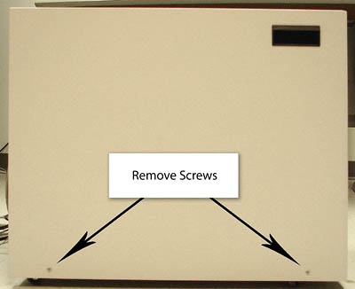
- Remove the two screws that secure the left side panel.
Figure 1. Screws on Left Side Panel
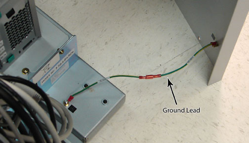
 note:
note:The side panel has a short ground lead connecting it to the main chassis. When removing the side panel, do not strain this ground lead.
Figure 2. Left Side Panel Ground Lead
- Remove the left side panel by lifting it up.
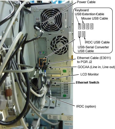
- Remove all the cables connected to the computer, ensure they
are properly labeled, and note their locations for reattachment.
Figure 3. HP Z400 Cable Configuration
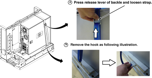
- Loosen the strap and remove the hook.
Figure 4. Removing Strap
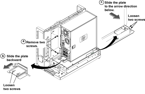
- Refer to the illustration below, and remove the Z400 computer
as follows:
- Remove the two screws securing the back bracket.
- Loosen the two screws on the back slide plate, and slide the plate backward.
- Loosen the two screws on the side slide plate, and slide the
plate in the direction of the arrow as shown below.
Figure 5. Removing HP Z400 Computer
- notice
- Carefully remove the computer using the back and bottom brackets from the GOC.

- Perform a disk wipe on all applicable hard drives in the old PC. See the latest revision of the Disk Management Tool Service Manual, PN 5500610-1EN available from the online documentation library.
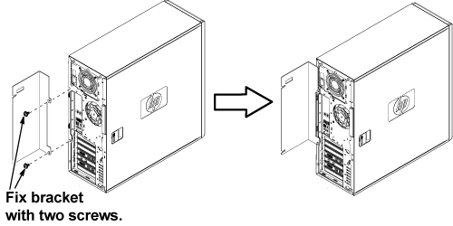
- Remove the back bracket from the defective computer, and install
it on the new computer.
Figure 6. Installing Back Bracket
- notice
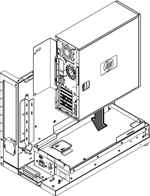
- Position the computer as shown below.
Figure 7. Computer Placement
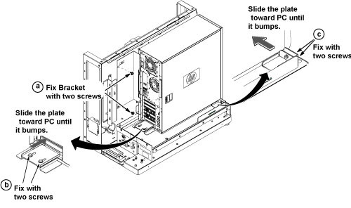
- To secure the computer:
- Attach the back bracket to the GOC frame with the two screws.
- Slide the back slide plate toward the computer until it aligns, and secure with the two screws.
- Slide the side slide plate toward the computer until it aligns, and secure with the two screws.
Figure 8. Securing Computer
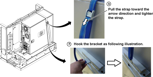
- Tighten the strap according as follows:
- Hook the bracket to the slot of the bottom plate.
- Pull and tighten the strap to secure the computer.
Figure 9. Tighten Strap
- Restore all cables to the computer.
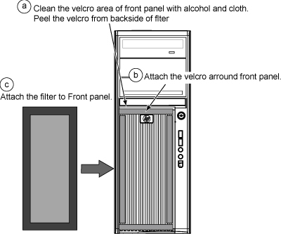
- Remove the dust filter from the old computer and attach it to
the new computer. If the old filter is not reusable, install a new
one.
Figure 10. Attaching Dust Filter
- Restore the GOC left side panel, and reconnect the ground lead to the left side panel.
|
Finalization
- Remove LOTO from the PDU and the GOC. See the MR Service Safety Manual, PN 5452735.
- Restore power to the GOC.
note:
If necessary, reconnect the optional UPS and ensure power is restored.
- Load software and applications onto the operating system. See Loading Host System Software (Quick Start). note:
Load From Cold (LFC) must be performed to properly transfer customer options.
- Update the eLicense with the new Host ID. See Software Option Installation with eLicense Generated Keys.
-
Repackage the defective PC for return.- notice
- Perform a scan to ensure the system and applications are working properly.