- id_12373697
- Version: 1.2
- Date: Jul 5, 2019 10:03:32 PM
GOC Power Distribution Supply Replacement
Prerequisites
| Required persons | Preliminary requirements | Procedure | Finalization |
|---|---|---|---|
| 1 | Not Applicable | 45 minutes | 30 minutes |
| Item | Quantity | Effectivity | Part number | Manufacturer |
|---|---|---|---|---|
| Standard and Phillips Screwdrivers and Pliers | 1 each | - | - | - |
| Item | Quantity | Effectivity | Part number | Manufacturer |
|---|---|---|---|---|
| Global Operating Console PDU | 1 | - |
5262750 |
- |
|

| Condition | Reference | Effectivity |
|---|---|---|
|
The host computer and GOCAA must be powered off as described below. |
- | - |
Powering Off Host and GOCAA
Shut Down Software
Procedure
- Click the Tools icon.
- On the Service Desktop Manager, click System Shutdown.
- Confirm the shutdown by clicking OK.
- Wait for the system to indicate on the monitor that it is safe
to power off the computer before proceeding. It usually takes about
90 seconds for this message to display.note:
Watch the screen and wait until the light turns yellow.
Remove Power to Operator Workspace
Procedure
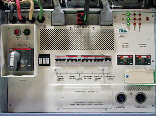
- Verify that the power indicator on the Operator Workspace is off.
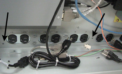
- Host circuit breakers are located on the front of the PDU.
Figure 1. Location of PDU Host/PC Breakers
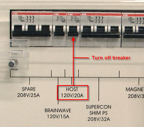
Move the host circuit breaker down to disconnect power.
Figure 2. Host Breaker
GOC Power Distribution Supply Replacement
Procedure
- Shut down system applications. Perform LOTO on the GOC before
continuing. See the MR Service Safety Manual,
PN 5452735.note:
Take extra precaution if the site has installed the optional GOC UPS accessory.
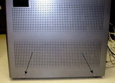
- Remove the screws that secure the left and right side panels
of the GOC.
Figure 3. GOC Left Panel
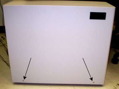
Figure 4. GOC Right Panel
- Disconnect the ground leads from both side panels.
Figure 5. Left Side Panel Ground Lead
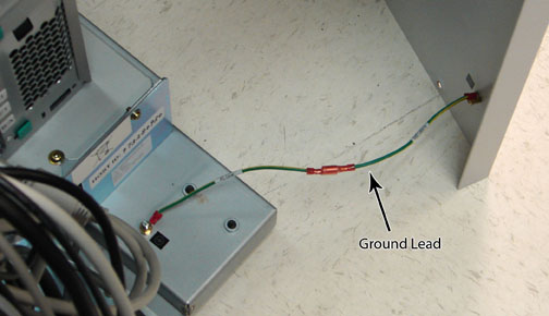
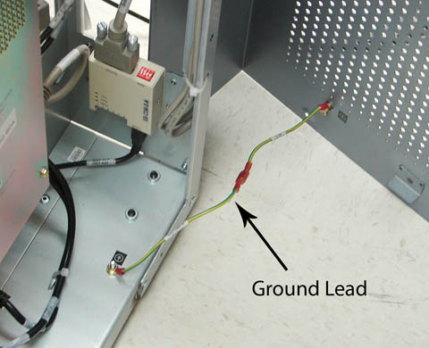
Figure 6. Right Side Panel Ground Lead
- Remove both GOC side panels and set aside.
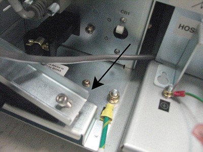
- Remove Strain Relief Plate (shown below) from the power cable.
Figure 7. Strain Relief Plate
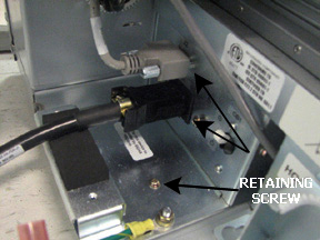
- Disconnect the power cable and connector from the GOC power
distribution supply, and remove the retaining screw from the plate.
Figure 8. Power Cable and Connector
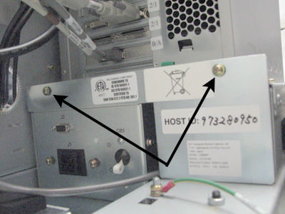
- Remove two screws from the side of the GOC power distribution
supply, and disconnect the AC power cables from the PDU.
Figure 9. Disconnecting AC Cables
- Remove the two screws at the top of the plate, and lift the
plate up to remove.
Figure 10. Removing Screws and Plate
- Carefully slide the GOC power distribution supply out of the GOC.
- Insert the replacement GOC power distribution supply. Reverse the preceding steps to properly install the replacement.
Finalization
Procedure
- Remove LOTO from the GOC power distribution supply. See the MR Service Safety Manual, PN 5452735.
- Turn the host and PC circuit breakers on the PDU back to the On position.
- Start the host computer by pressing the On button, and log in. note:
It is possible that the customer changed the default password. If you cannot log in, contact the customer for the correct password.
- When the system is fully booted, perform a scan to ensure proper operation of the system.