- id_12373994
- Version: 1.10
- Date: Dec 16, 2019 12:34:22 PM
HP Z420 Computer Replacement
Prerequisites
| Required persons | Preliminary requirements | Procedure | Finalization |
|---|---|---|---|
| 2 | Not Applicable | 120 minutes | 30 minutes |
| Item | Quantity | Effectivity | Part number | Manufacturer |
|---|---|---|---|---|
| Screwdriver set | 1 | - | - | - |
| Item | Quantity | Effectivity | Part number | Manufacturer |
|---|---|---|---|---|
| HP Z420 computer | 1 | - | - | - |
| Side holder bracket | 1 | - |
See the FRU manual. |
- |
| Back holder bracket | 1 | - |
See the FRU manual. |
- |
| Dust filter (if needed) | 1 | - | - | - |
|


Overview
This procedure provides instruction to replace the HP Z420 host computer with another HP Z420.
Prepare Workstation for Host Computer Removal
Procedure
- Ask the customer to archive all images to an external storage device such as a PACS or DVDs.
- Perform a Save Info.
- Shut down the host computer.
The GOC supports an optional UPS. Confirm your site’s configuration.
- Perform LOTO on the GOC/operator workspace. See the MR Service Safety Manual, PN 5452735. For added protection, disconnect the twist-n-lock main power cable from the rear of the console.
Remove Host Computer from GOC
Procedure
- Remove the two screws that secure the left side panel of the GOC.note:
The side panel has a short ground lead connecting it to the main chassis. When removing the side panel, do not strain this ground lead.
Figure 1. Left Side Panel Ground Lead
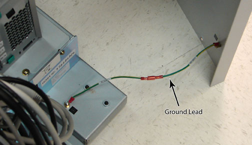
- Disconnect the short ground lead that connects the side panel to the GOC main chassis at the center of the lead.
- Remove the left side panel and set it is a safe place.
- Remove all the cables connected to the host computer.
Confirm that the cables are properly labeled. Note their locations for reattachment.
Figure 2. HP Z420 Cable Configuration
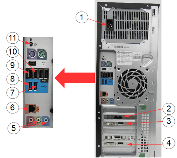
Item Description 1 Power supply 2 Ethernet cable to PGR J2 3 IRDC connection to LCD monitor 4 System monitor connection to LCD monitor 5 GOCAA (line in, line out) 6 Ethernet switch 7 IRDC USB ports 8 USB serial converter 9 Keyboard USB extension cable 10 Mouse USB cable 11 Rear power button - Loosen the strap and remove the hook.
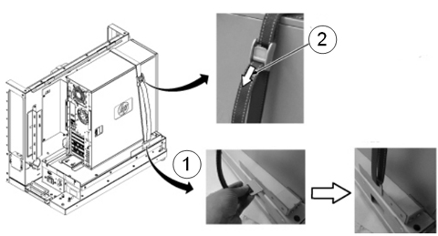
Figure 3. Removing Strap
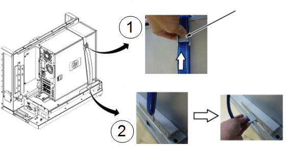
Item Description 1 Press release lever of buckle and loosen strap. 2 Remove the hook. - Remove the host computer from the GOC.
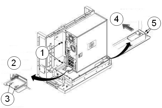
Figure 4. Removing HP Z420 Computer from GOC
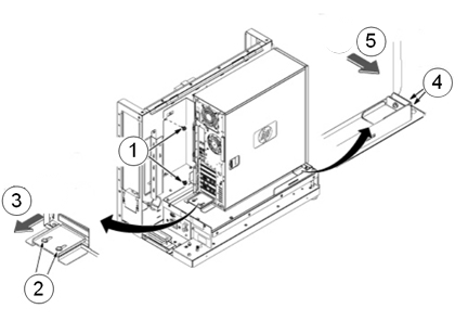
Item Description 1 Remove the two screws securing the back bracket to the GOC. 2 Loosen the two screws on the back slide plate. 3 Slide the plate backward. 4 Loosen the two screws on the side slide plate. 5 Slide the plate in the direction of the arrow. - Carefully remove the computer using the back and bottom brackets.
- Perform a disk wipe on all applicable hard drives in the old PC. See the latest revision of the Disk Management Tool Service Manual, PN 5500610-1EN available from the online documentation library.
Install New Host Computer
The replacement computer may have two Torx/slot screws (not Phillips) that must be removed before attaching the back bracket. Remove the screws using a slot screwdriver. Install the Torx/slot screws into the defective computer before returning it for repair.
Procedure
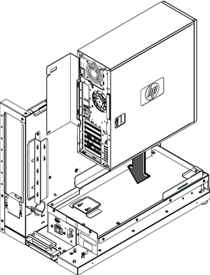
- Position the computer in the GOC as shown below.
Figure 5. Computer Placement
- To secure the computer:
Figure 6. Securing Computer
Item Description 1 Transfer the back bracket to the new host and secure with the two screws. 2 Slide the plate toward the PC until it bumps. 3 Secure with two screws. 4 Slide the plate toward the PC until it bumps. 5 Secure with two screws. - Tighten the strap as follows:
- Hook the bracket to the slot of the bottom plate.
- Pull and tighten the strap to secure the computer.
Figure 7. Tighten Strap
Item Description 1 Insert the strap hook into the bracket. 2 Pull the strap in the direction of the arrow and tighten. - Restore all cables to the computer.
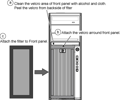
- Remove the dust filter from the old computer. Remove the Velcro strips from the inside of the front cover of the old machine and the dust filter. Attach them to the inside of the new machine’s cover. Attach the Velcro strips to the dust filter. Install the dust filter. If the old filter is not reusable, install a new one.
Figure 8. Attaching Dust Filter
- Retrieve the GOC left side panel and reconnect the ground lead to the left side panel.
- Attach the GOC left side panel with the two screws.
Finalization
Procedure
- Remove LOTO from the GOC to return power. See the MR Service Safety Manual, PN 5452735. If needed, reconnect the twist-n-lock main power cable to the rear of the console.
- Power up host computer.
- Verify that the host computer front panel power LED is illuminated as a steady blue signal.
- Load software and applications onto the operating system.
See Loading Host System Software (Quick Start).
note:The HP Z420 host computer only supports DV25.
Load from cold (LFC) procedure must be performed to properly transfer customer options.
- Update the eLicense with the new host ID. See Software Option Installation with eLicense Generated Keys.
- Perform Check Scan to confirm the system and applications are working properly.
- Confirm that all customer functions are operational (auto voice, filming, network, archive).
- Repackage the defective PC for return.