- 00000018WIA300D1130GYZ
- id_152711053.4
- Aug 10, 2020 2:51:11 PM
Front Cover Removal and Installation
Prerequisites
| Personnel requirements | |||
|---|---|---|---|
| Required persons | Preliminary requirements | Procedure | Finalization |
| 1 | - | 15 minutes for front cover; 30 minutes for GEM light strips | 15 minutes |
| Tools and test equipment | |||
|---|---|---|---|
| Item | Quantity | Part number | Manufacturer |
| Pair: Cut-Resistant Gloves | 1 | - | - |
| Nonmagnetic Titanium Service Tool Kit, Large Set | 1 | 5112581 | - |
| EPX Plus II Applicator | 1 | 5265376 | - |
| Mixing Nozzle, 3M Scotch-Weld EPX Applicator, 50 ml, PN 62-9154-9148-4 or Equivalent | 1 | 46-252065P154 | - |
| Consumables | |||
|---|---|---|---|
| Item | Quantity | Part number | Manufacturer |
| Plexus MA300 Adhesive, 50 ml | 1 | 5774729 | - |
| Adhesive Cable Tie Mount | 1 | 46-208747P1 | - |
| DV Light Assembly | 1 | 5766238 | - |
| 5.6 inch Cable Tie | 1 | 46-208758P2 | - |
| Replacement parts | |||
|---|---|---|---|
| Item | Quantity | Part number | Manufacturer |
| Front Cover | 2 | See FRU manual | - |
| Lighting Assembly | 2 | See FRU manual | - |
| ||||
About this task
Overview
This document contains the procedures for front cover removal and installation. The front covers consist of two halves and contain the emergency stop and control panels for the system.
Instructions for replacing the light strips are also included.
Preliminary
Procedure
- Turn off and perform LOTO on the RF and PEN cabinets. See the MR Service Safety Manual, PN 5452735.
- Undock the patient table and position the table away from the magnet.
Front Cover Removal
About this task
The type and order of the side cover removal depends on the components accessed. For left or right front cover removal, remove the corresponding side middle and side front covers first.
Procedure
- Remove the side covers (see Side and Top Cover Removal and Installation).
Figure 1. Front Cover Screw Locations 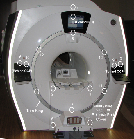 Note:
Note:Remove screws in the order listed. Screw locations shown above are approximate and may be hidden under unremoved components.
Vertical Light Strip Replacement
About this task
For left or right light strip removal, remove the corresponding side middle and side front covers.
Procedure
- Disconnect the power cord from the corresponding light strip.
Figure 2. Disconnect the light strip power cord 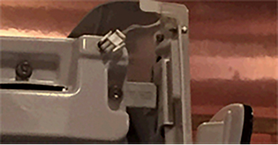
- Remove the translucent light cover.
Figure 3. Remove the translucent light cover 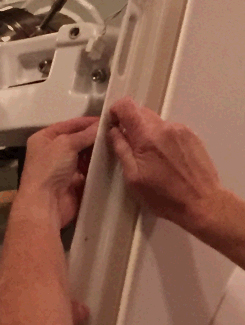
- Remove the clips holding the lights to the cover. Cut the wire ties on the back side holding the light strip wire and remove the light strip.
Figure 4. Remove the clips 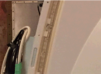
Figure 5. Cut the wire tie holding the strip wire 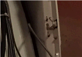 Note: If the current LEDs in the cover are already mounted to adhesive mounts, proceed to Step 10.
 - CAUTION: Nitrile gloves must be worn when using alcohol wipes and glue.Assemble the glue gun applicator using the 1:1 plunger, following the manufacturer's instructions included in the box. Make sure to connect the glue and mixing nozzle to the applicator assembly.
Figure 6. Glue gun with 1:1 plunger 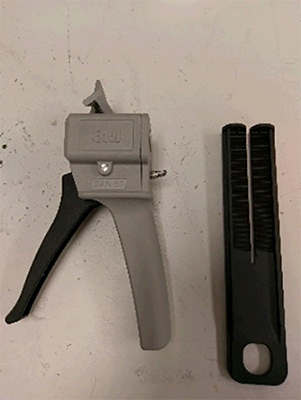
Figure 7. Assembled glue gun 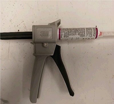
- Clean the location where the adhesive mounts will be installed using the alcohol wipes provided in the FRU kit.
Figure 8. Clean the LED groove 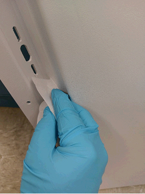
- Install the adhesive mounts into the LED groove. Make sure to install one at the top and one at the bottom of the cover, with the remaining 9 spaced approximately 200 mm apart in the LED groove. Placement is not critical, but should span the whole groove.
Figure 9. Adhesive mount installation and placement 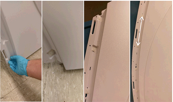
- Using the gun applicator, liberally apply glue to the vertical sides of the adhesive mounts. Wait until the glue is no longer tacky (approximately 10 minutes) before continuing to the next step.Note: It is critical that glue coverage does not extend outside of the LED groove, and that glue does not interfere with the slots for cable tie installation.
Figure 10. Glue application 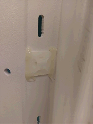
- Install the LED strip starting from the bottom to the top of the panel, pealing the backing off the LED strip (approximately 12 inches) to expose the adhesive tape, and continuing up the side as the LED strip is placed. Between adhesive mounts, make sure to press the LED onto the cover to eliminate any gaps.
Figure 11. LED installation 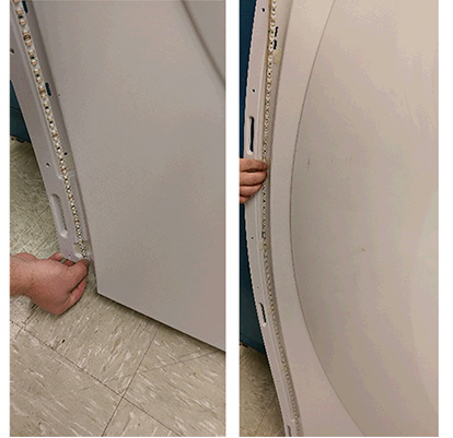
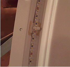
- Loop the cable ties through the adhesive mounts, locking the LEDs in place.
Figure 12. Cable tie installation 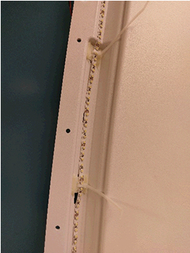
- Clip the excess from the cable ties.
Figure 13. Clip excess cable tie 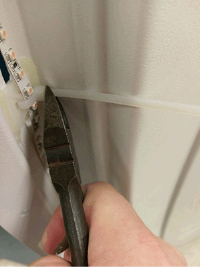
Figure 14. Proper LED placement