
- 00000018WIA303AF030GYZ
- id_123738881.16
- Sep 2, 2020 2:33:10 PM
PAC and SRI-4 Replacement
Prerequisites
| Required persons | Preliminary requirements | Procedure | Finalization |
|---|---|---|---|
| 1 | Not Applicable | 30 mins. for PAC; 45 mins. for SRI | 30 minutes |
| Item | Quantity | Effectivity | Part number | Manufacturer |
|---|---|---|---|---|
| Nonmagnetic service tool kit | 1 | - |
5112581 | - |
| Item | Quantity | Effectivity | Part number | Manufacturer |
|---|---|---|---|---|
| PAC-2BV FRU | 1 | - | - | - |
| PAC-2B FRU | 1 | - | - | - |
| PAC-5 FRU | 1 | - | - | - |
| ||||
About this task
Overview
This procedure explains replacement of the physiological acquisition controller (PAC) assembly and the scan room interface (SRI-4) on a fixed site system.
The systems may have either a PAC-2B, a PAC-2BV, or a PAC-5. The PAC-5 is backward compatible with the PAC-2B/PAC-2BV. There is no impact with PAC hardware configuration in Guided Install.
Removal of the PAC
Procedure
- The PAC is behind the left side middle cover.
Figure 1. PAC Location 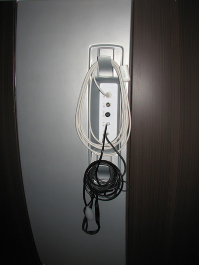
- Disconnect all cables from the I/O panel except the white PPG
cable, which is permanently attached.
- Remove the left side covers to access the PAC. See Side and Top Cover Removal and Installation.
- Carefully pass the PPG cable through the opening in the left side middle cover. Avoid damage to the cable while removing the cover.
Figure 2. General Location of PAC and SRI (RRx Systems) 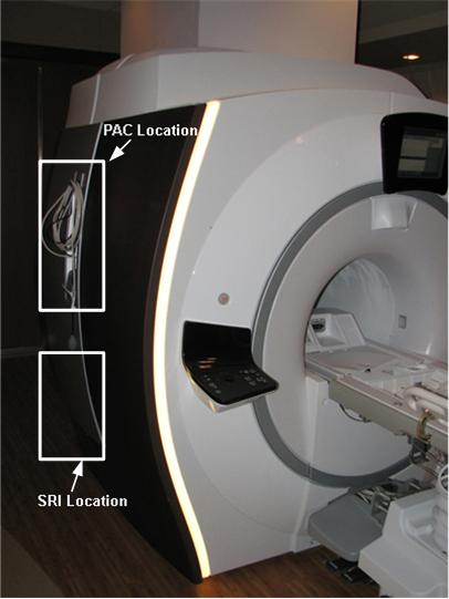
Figure 3. Location of PAC and SRI (DPP Systems) 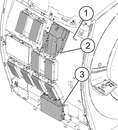
ITEM DESCRIPTION 1 Left side 2 PAC 3 SRI-4
Installation of the New PAC
Procedure
- Check the alignment of the PAC with the enclosure in all three
planes.
-
There are adjustment screws that allow for adjustment up/down, left/right, and in/out.
-
Adjust the PAC I/O panel so that it lines up with the slot in the enclosure in the left/right and up/down plane, and adjust it in/out so the gap between the I/O panel and the enclosure is less than 1 mm.
Figure 4. PAC Alignment (RRx Systems) 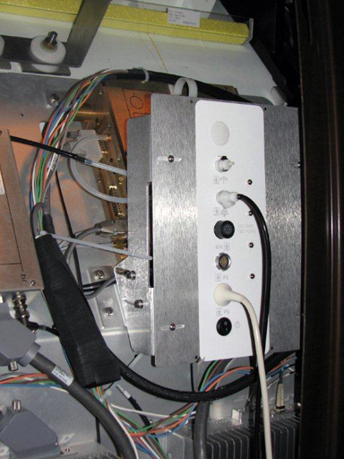
Figure 5. PAC Alignment (DPP Systems) 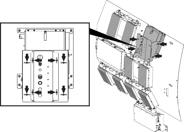
-
Removal of the SRI
Procedure
- Disconnect the cables attached to the SRI.
Figure 6. SRI Cable Map 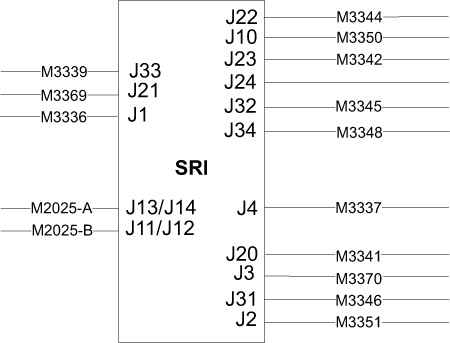
Installation of the New SRI
Procedure
- Place the new SRI in the proper location, and install in the reverse order of how it was removed.
- Mount the removed temperature sensor box on the replacement SRI.
- Reconnect the cables and replace the enclosure panels.
- Remove LOTO and restore power to the system. See the MR Service Safety Manual, PN 5452735.
Finalization
Procedure
- Perform a TPS reset.
- Confirm that the reported problem has been resolved by running PAC or SRI diagnostics. In Service Methods, instructions for these diagnostics can be found in Troubleshooting > Diagnostics > Hardware Location > Magnet Room > PAC Diagnostic Tests and SRI Functional Diagnostics.
- Perform a Check Scan.