Use proper LOTO procedures before servicing and/or maintaining.
Warning
Ferrous material hazard
The mounting bracket, encoder, and drive motor contain ferrous material.
Holding this assembly too close to the magnet bore will forcibly attract it to the magnet. To prevent possible bodily injury or material damage, use two people to promptly remove mounting bracket assembly from magnet room.
Warning
Personal injury and equipment damage
If the magnet is energized, tools and loose materials that contain ferrous material will be strongly attracted to the magnet and may become dangerous projectiles.
When servicing any magnetic equipment, it is critically important that the service engineer consciously plan the path to be taken when moving highly ferrous devices within the magnet environment. The path should be as far from the magnet as practical and avoid high flux-density fields.
Movement of ferrous material in the magnet room must follow the GE service procedure for that device.
When exiting, move away from the magnet in the most direct manner possible. Except when moving ferrous material to and from its native location on or near the magnet, the static magnetic field in any portion of the service path shall not exceed 200 Gauss.
Two (2) MR safety trained personnel must be present at all times when servicing highly ferrous devices in the areas of magnetic fields.
When planning a service path, it is critical that the path be clear and sufficiently wide. Make sure that there are no trip hazards, obstacles, clutter, slippery surfaces, or other items even partially restricting the path. If there are portable obstacles in a path, remove them from the area and replace them after the service action is completed. It is required to walk the path prior to beginning service to ensure that there is sufficient space through which to pass for yourself and the object being serviced.
CAUTION
In order to safely service items in the rear pedestal, according to the Preinstallation Manual (PIM), the minimum distance between the back of the magnet enclosures and the rear wall must be 66 inches (1676 mm) for MR750 and MR450 and 53 inches (1346 mm) for MR450w. If the site is operating under a room size deviation and space is not provided, follow the proper procedure to remove the rear pedestal from the room to service it.
About this task
Overview
This procedure covers the replacement of the longitudinal drive
motor and encoder, which are both located on the same rear pedestal
bracket assembly.
Removing Drive Motor/Encoder Bracket Assembly
Procedure
Drive the LPCA to within 1 ft (30 cm) of the end of the rear
pedestal.
Perform LOTO on the RF amplifier and PEN cabinet (magnet room).
See the MR Service Safety Manual, PN 5452735.
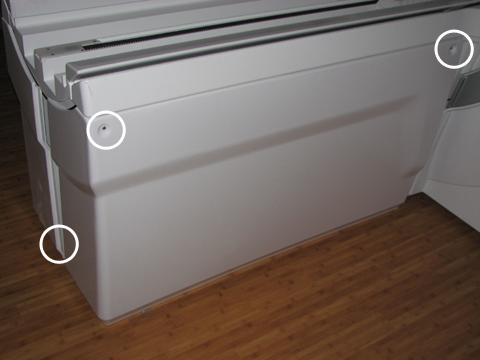
Remove the right rear pedestal cover by removing two screws
on the right side and one rear screw. Lift up the cover out of the
bottom support brackets.
Figure 1. Rear Pedestal Screw Locations
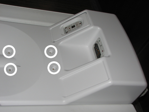
Remove the cover from the LPCA by removing the four screws.
Figure 2. LPCA Cover Screw Locations
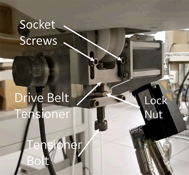
Loosen the two socket screws on drive belt tensioner, and then
loosen the tensioner bolt until the belt becomes loose.
Figure 3. Drive Belt Tensioner
Loosen the two nuts of the rear position belt clamp and pull
the belt out of the LPCA.
Figure 4. Belt Clamp
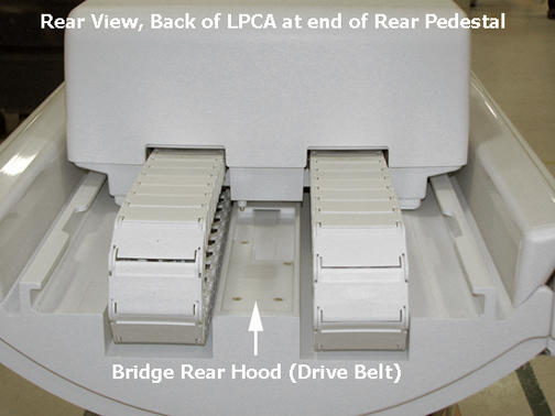
Remove the bridge rear hood by removing the four screws.
Figure 5. Rear Pedestal Rear Hood
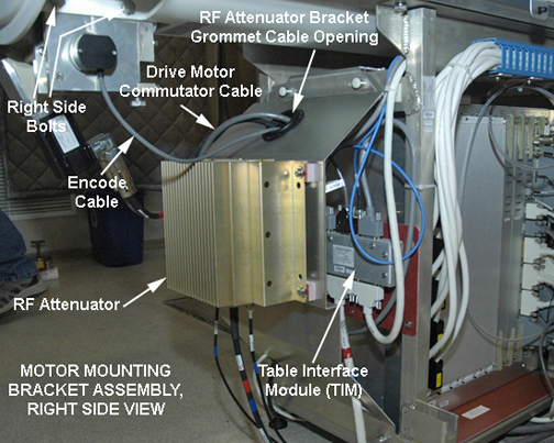
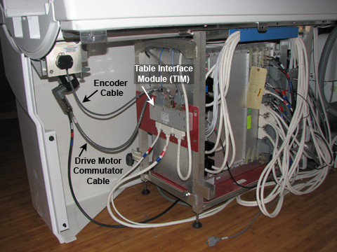
Disconnect the drive motor commutator cable from the Table Interface Module (TIM) at J3, and disconnect J1 and J2 at the motor assembly.
Figure 6. Cable Path from Table Interface Module to Drive Motor/Encoder
Note:
The right pedestal cover is shown installed for picture clarity only.
Disconnect the drive motor encoder cable from the TIM at J2.
Warning
Ferrous material hazard
The mounting bracket, encoder, and drive motor contain ferrous material.
Holding this assembly too close to the magnet bore will forcibly attract it to the magnet. To prevent possible bodily injury or material damage, use two people to promptly remove mounting bracket assembly from magnet room.
Loosen (do not remove) the four M10 head bolts (two on each
side) from the motor mounting bracket assembly using a 17 mm socket
wrench.
Note:
Have one person hold the assembly while loosening or reinstalling
it to prevent cross threading.
Carefully remove the two M10 bolts and lock-washers on one side
while holding the bracket assembly in place, then remove the bolts
and lock-washers on the other side. The assembly drops straight down
from the bottom of the bridge. Handle with care in the magnetic field.
Carefully maneuver the drive belt from the rear of the LPCA
through the bracket assembly.
Installing Drive Motor Assembly
Procedure
Warning
Ferrous material hazard
The mounting bracket, encoder, and drive motor contain ferrous material.
Holding this assembly too close to the magnet bore will forcibly attract it to the magnet. To prevent possible bodily injury or material damage, use two people to promptly remove mounting bracket assembly from magnet room.
Rethread the belt through the new long drive assembly. Hold the bracket assembly in place while replacing the two M10 bolts and lock washers on each side.
Note: Set the front belt clamp to show 3 exposed belt teeth and set the back belt clamp to show 15 exposed belt teeth.
Tighten the tensioner bolt clockwise until the drive belt tensioner is at the top of its travel and the socket screws bottom out in the slots. Tighten the tensioner socket screws. See Figure 3.
Replace the bridge rear hood by angling the hood onto the bridge
and securing it with four brass M4 screws.
Reattach the drive motor commutator cable to J3 and the encoder
cable to J2 on the Table Interface Module (TIM). See Figure 6
Replace the LPCA cover with the four brass M6 pan head screws
using a medium slotted screwdriver.
Remove LOTO. See the MR Service Safety Manual, PN 5452735.
Drive the LPCA to the front of the magnet home position.

 Note:
Note: Note:
Note: