
- 00000018WIA30E7F030GYZ
- id_123749281.17
- Jan 17, 2020 10:20:24 AM
Magnet Microphone Replacement
Prerequisites
| Required persons | Preliminary requirements | Procedure | Finalization |
|---|---|---|---|
| 2 | Not Applicable | 60 to 120 minutes | Not Applicable |
| Item | Quantity | Effectivity | Part number | Manufacturer |
|---|---|---|---|---|
| Non-Ferrous Service Tool Kit | 1 | - |
5112581 | - |
| Item | Quantity | Effectivity | Part number | Manufacturer |
|---|---|---|---|---|
| A-Port Legacy Cable Track Assembly | 1 | - |
See FRU Manual | - |
| Rear Microphone Assembly | 1 | - |
See FRU Manual | - |
| Front Microphone Assembly | 1 | - |
See FRU Manual | - |
About this task
Overview
This document describes the removal and installation of the rear and front microphones. The rear microphone is located inside the LPCA and the front microphone is attached to the front end bell. Both microphones connect to the SRI.
Replacing Rear Microphone
About this task
Before replacing a microphone, plug the replacement into the SRI (J31) to verify that the replacement microphone fixes the problem.
Procedure
- Remove the LPCA cover (four screws).
Figure 1. Removing LPCA Cover 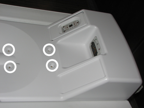
- Pull the microphone and housing out of the LPCA.
Figure 2. Removing Microphone and Housing from LPCA 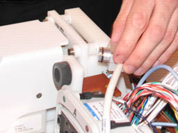
- Remove the microphone from its housing by gently pulling the
microphone to the rear.
Figure 3. Removing Microphone from Housing 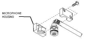
- The rear microphone attaches to the SRI (located on the side
of the magnet) at J31.
Figure 4. SRI Cable/Connections 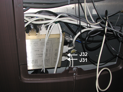
Removal and Installation of Front Microphone
About this task
Before replacing a microphone, plug the replacement into the SRI (J32) to verify that the replacement microphone fixes the problem.
Procedure
- Disconnect the other end of the microphone cable at J32 located
on the SRI.
Figure 5. SRI Cable Connections - Remove the four screws from the old microphone assembly on the
end bell and detach the housing and cable from the cover. The cover
of the old microphone assembly should remain attached to the end bell
as it is epoxied in place. Remove the old o-ring from this cover.
Discard the old assembly and cable.
Figure 6. Microphone Placement on Front End Bell 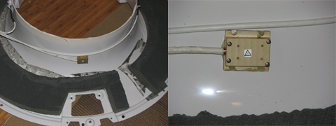
Finalization
Finalization
-
Remove LOTO from the PDU. See the MR Service Safety Manual, PN 5452735.
-
Verify that the microphone is functioning properly.