• Object ID: 00000018WIA3069AE20GYZ
  • Topic ID: id_13105835 Version: 3.5
  • Date: Feb 6, 2020 1:42:26 PM

Front end bell removal and installation

Prerequisites

Table 1. Personnel requirements
Required personsPreliminary requirementsProcedureFinalization
2Not Applicable1.5 hoursNot Applicable
Table 2. Tools and test equipment
ItemQuantityEffectivityPart numberManufacturer
Nonmagnetic Titanium Service Tool Kit, Large Set--5112581-
Table 3. Replacement parts
ItemQuantityEffectivityPart numberManufacturer
Front End Bell Assembly1-

See FRU Manual

-
Table 4. Safety

Procedure

  1. Perform LOTO on the PDU. See the MR Service Safety Manual, PN 5452735.
  2. Move the patient table away from the magnet. Press the Table Home sensor on the dock, and drive the LPCA toward the rear of the bridge.
  3. Remove the trim rings.
  4. Remove the bridge cover.
  5. Remove the laser cover.
    Note: You do not need to remove the In-Room Display (IRD) to remove the front end bell.
  6. Remove the bridge assembly. See Bridge and Longitudinal Drive Belt Replacement.
    Figure 1. Front end bell
  7. Remove the front body coil bias cable(s) and the body coil ID cable.
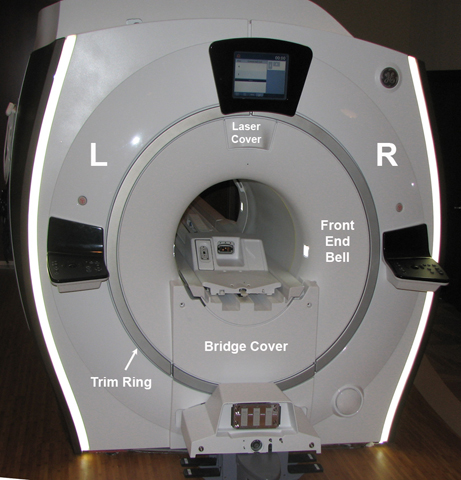
  8. Remove the L-brackets from the vibration bracket.
    Figure 2. L-Bracket removal
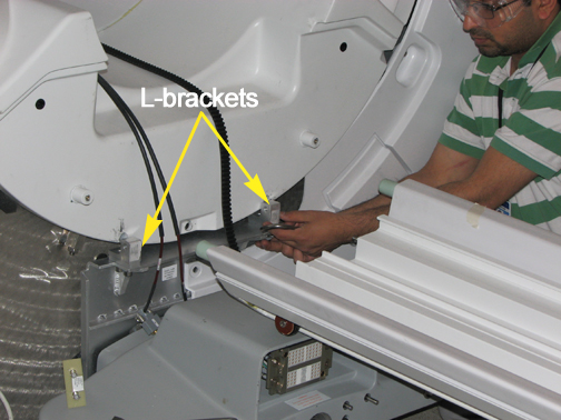
  9. Remove the screws holding the front end bell to the arm brackets.
    Figure 3. Front end bell screws
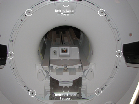
  10. Monitor the slack in the cables as the end bell is removed. The cables should have enough slack to place the end bell on the floor to the left of the front of the magnet.
  11. Notice: The front end bell is heavy. Avoid awkward body positioning. Use proper lifting techniques when moving the front end bell.
    Remove the end bell.
    Note: Take care when removing or installing the end bell. Do NOT touch or move the body coil. Body coil tuning is dependent on body coil location.
  12. Disconnect the cables for the microphone and the bore light.
  13. Reverse the steps to install the replacement front end bell. Confirm that the gap between the front end bell and the RF body coil is between 2.0 mm and 5.0 mm with a desired gap of 2.0 mm. Verify the proper fit of the covers.

    If the gap measurement is outside the desired range, see RF Body Coil Replacement.

Finalization

  1. Remove LOTO from the PDU. See the MR Service Safety Manual, PN 5452735.
  2. Ensure the microphone and bore lights work.
  3. Complete a body scan (see Doing a check scan).