
- 00000018WIA3000BE20GYZ
- id_131059303.1
- Nov 27, 2019 10:19:09 AM
Replacing Operator Display, Control Panels, and E-Stop Buttons
Prerequisites
| Required persons | Preliminary requirements | Procedure | Finalization |
|---|---|---|---|
| 1 | 5 minutes | 45 minutes | 5 minutes |
| Item | Quantity | Effectivity | Part number | Manufacturer |
|---|---|---|---|---|
| Non-Magnetic Service Tool Kit | 1 | - |
5112581 | - |
| Item | Quantity | Effectivity | Part number | Manufacturer |
|---|---|---|---|---|
| In-Room Display (IRD) | 1 | - |
See FRU Manual | - |
| Trackball Control Panel (Left or Right) | 1 | - |
See FRU Manual | - |
| E-Stop Panel | 1 | - |
See FRU Manual | - |
| IRD Pivot Bracket Assembly | 1 | - |
See FRU Manual | - |
| ||||
About this task
This procedure describes the removal and installation of the operator display, control panel, E-stop, and IRD pivot bracket assembly.
Replace In-Room Display (IRD)
Procedure
- Remove the two outer bracket covers, held by two screws each.
Figure 1. Outer Bracket Cover Screws (Left Side View) 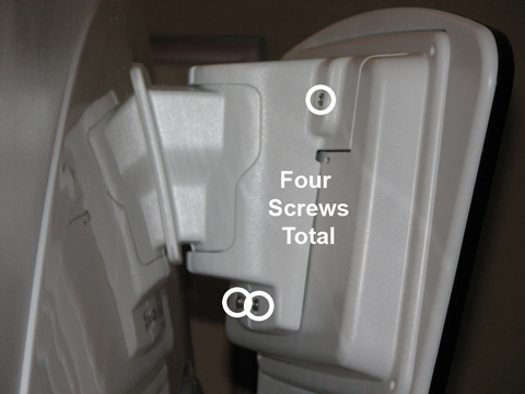
- Remove the two inner bracket covers, held by two screws each.
Figure 2. Inner Bracket Cover Screws (Right Side View) 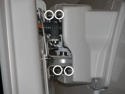
- Disconnect three cables attached to the IRD (ground cable, fiber
optic cable, and power cable).
Figure 3. IRD Cables 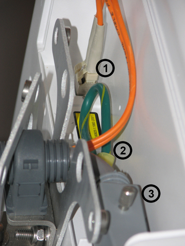
Remove the bottom two screws and loosen the top two screws holding the bracket plate to the back of the IRD. Lift the monitor up and off the bracket carefully, because eddy currents may pull against it.Warning Figure 4. IRD Bracket Plate Screws 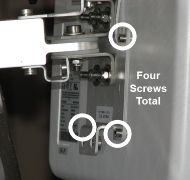
- Press the EMO reset button to return the system to normal operation.
Figure 5. EMO Reset Button 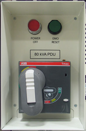
Replace Operator Control Panel (OCP)
About this task
Procedure
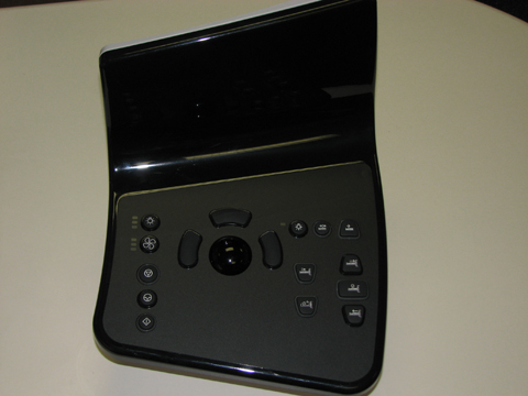
Disconnect the three cables from the back of the OCP and remove it.Warning 
Figure 7. OCP Cables 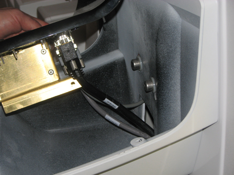
- Press the EMO reset button to return the system to normal operation.
Figure 8. EMO Reset Button
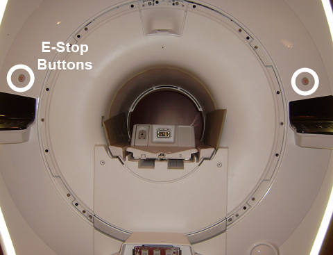
Replace E-Stop Button/Panel
About this task
Procedure
- Disconnect the E-stop button cable from the OCP (see Replace Operator Control Panel (OCP)).
Figure 10. E-Stop Button Cable 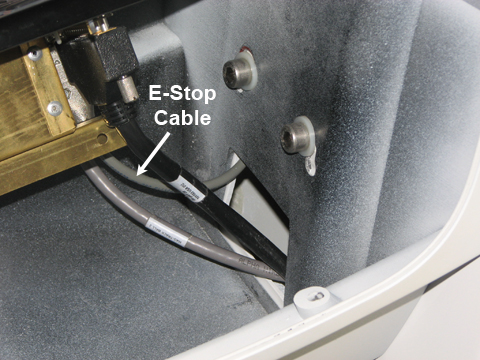
- Press the EMO reset button to return the system to normal operation.
Figure 11. EMO Reset Button
Replace IRD Pivot Bracket Assembly
Procedure
- Remove the cable clamp from the pivot bracket and move the IRD
cable out of the way.
Figure 12. Pivot Bracket Cable Clamp (Right Side View) 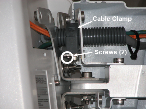
- Remove the two screws holding the pivot bracket assembly to
the bracket/plate mounted on the magnet.
Figure 13. Pivot Bracket Assembly 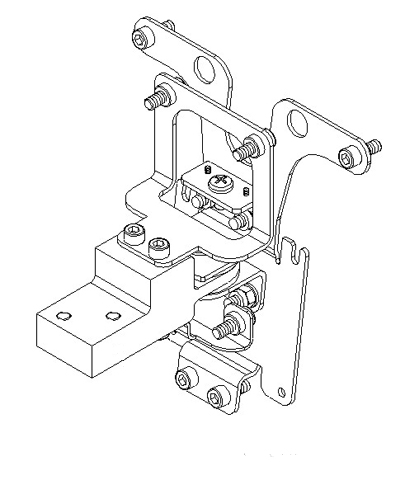
- Press the EMO reset button to return the system to normal operation.
Figure 14. EMO Reset Button