
- 00000018WIA307ED030GYZ
- id_123747211.13
- Aug 14, 2019 8:02:19 PM
GEM Dock Connector Replacement
Prerequisites
| Required persons | Preliminary requirements | Procedure | Finalization |
|---|---|---|---|
| 2 | - | 90 mins for non–GEM; 110 mins for GEM | 15 minutes |
| Item | Quantity | Effectivity | Part number | Manufacturer |
|---|---|---|---|---|
| MCRv tool (1.5T) | 1 | - |
5182417 | - |
| Non-magnetic tool kit | 1 | - |
5112581 | - |
| Item | Quantity | Effectivity | Part number | Manufacturer |
|---|---|---|---|---|
| Loctite 242 Threadlocker, medium strength | 0.5CC | - | - | - |
| Item | Quantity | Effectivity | Part number | Manufacturer |
|---|---|---|---|---|
| Self-Locking Cable Tie | 5 | - |
46-208758P3 | - |
| Harness, ODU, GEM, Dock Side P2 | 1 | - |
See FRU Manual | - |
| Harness, ODU, GEM, Dock Side P3 | 1 | - |
See FRU Manual | - |
| Harness, ODU, GEM, Dock Side P4 | 1 | - |
See FRU Manual | - |
| ||||||||||||
About this task
Overview
The dock contains three connector plates that pass data from the patient table to the RF hub. Signals flow from the table to the system by way of several cables with connecting points. The most important connection takes place where the patient table connects to the magnet via the dock. This document describes replacing the dock side of this connection.
When the patient table and dock are connected, data travels between two types of connectors: coax for RF signal and pin/socket for control.
Removing Dock from Magnet Room
Procedure
- Follow the instructions in Dock Removal and Installation to remove the dock from the magnet room.
- Proceed to the next section.
Removing Dock Connector Plate
Procedure
- When the dock is outside of the magnet room, using a 3/4-inch
wrench, remove four bolts (two on each side) to unfasten the dock
cover from the dock base.
Figure 1. Side View of Dock 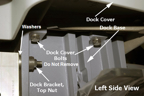 Note:
Note:Be sure to disconnect the dock switch connector when removing dock cover.
- Remove the two Allen head screws from the ODU P connector being
replaced.
Figure 2. Dock Cover Upside-Down View 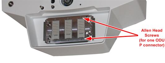
- Cut the cable tie for the ODU P connector harness being replaced.
Figure 3. Dock Cable Ties (Rear View of Dock) 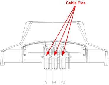
Installing Dock Connector Plate
Procedure
- Route the replacement dock harness through the opening in the dock cover.
- Reattach the ODU P connector to the dock connector plate.
Replace cable ties for the harness on the dock cover.Notice - Carefully turn the dock cover right side up, reconnect the dock switch connector, and place the dock back on the dock base. Reattach the dock bolts. (See Figure 1.)
Installing Dock
Procedure
- Follow the instructions in Dock Removal and Installation to install the dock.
- Proceed to Finalization.
Finalization
Procedure
Verify proper operation of the table.
- Dock the table.
- Verify proper up and down table motion.
- When the table is in a fully raised position, verify that the table is level with the bridge.
- Verify that raising the table to full height results in the LPCA automatically driving out to engage the cradle.
- When the table is in a fully raised position, verify that the cradle and the LPCA can be advanced normally into the bore.
- Verify that lowering the table results in automatic retraction of the LPCA into the bridge.
- Verify normal cradle and LPCA motion from home position to end of travel on the bridge using enclosure In Fast and Out Fast buttons at the Operator Console.
- Verify that the emergency release and side latches work properly.