
- 00000018WIA30D8AE20GYZ
- id_131058723.5
- Feb 6, 2020 1:58:19 PM
Room ambient and bore temperature sensors replacement
Prerequisites
| Required persons | Preliminary requirements | Procedure | Finalization |
|---|---|---|---|
| 1 person for each sensor replacement procedure | Not Applicable | 5 hours for bore temperature sensor; 1 hour for room ambient temperature sensor | 15 minutes |
| Item | Quantity | Effectivity | Part number | Manufacturer |
|---|---|---|---|---|
| Digital Volt Meter (DVM) | 1 | - | - | - |
| Nonmagnetic Titanium Service Tool Kit, Large Set | 1 | - | 5112581 | - |
| Item | Quantity | Effectivity | Part number | Manufacturer |
|---|---|---|---|---|
| Bore Temperature Cable and Sensor (Run 3350, MAG-SRI-J10 to Mag-Bore, Bore Temp Sensor) | 1 | - |
See FRU Manual | - |
| Room Ambient Temperature Sensor | 1 | - |
See FRU Manual | - |
| Condition | Reference | Effectivity |
|---|---|---|
| No required conditions. | - | - |
About this task
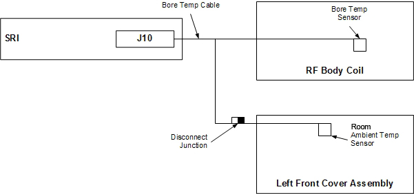
This procedure describes the replacement of the two temperature sensors associated with the magnet. The room ambient temperature sensor is located in the left front cover. The room ambient temperature sensor is clamped into the left cover, so the sensor can be replaced without replacing the cover. The patient bore temperature sensor is located inside the RF body coil. The room ambient temperature cable plugs into the bore temperature cable Figure 1. The bore temperature cable then connects to the SRI at J10.
Room ambient temperature sensor replacement
Procedure
- Remove the left side middle and left side front covers.
See Side and Top Cover Removal and Installation.
The room ambient temperature sensor is located behind the front cover.
Figure 2. Room ambient air temperature sensor 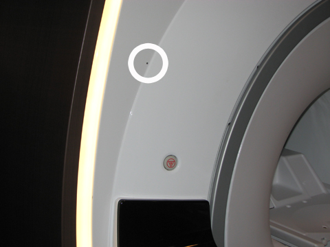
- Disconnect the room ambient temperature sensor from the bore temperature sensor cable. The room ambient temperature sensor cable is approximately 72 inches (180 cm) long, and the connector is either near the bottom of the front left cover or near the sensor.
Figure 3. Room ambient temperature connector and sensor 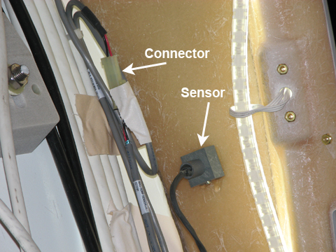
Patient bore temperature sensor replacement
Procedure
- Route the new cable through the magnet enclosure and tape it
to the RF body coil at the 315 position. Reconnect the bore temperature
sensor cable at J10 on the SRI under the left side of the magnet enclosure,
and reconnect the room ambient temperature sensor cable.
Figure 4. Bore temperature sensor cable 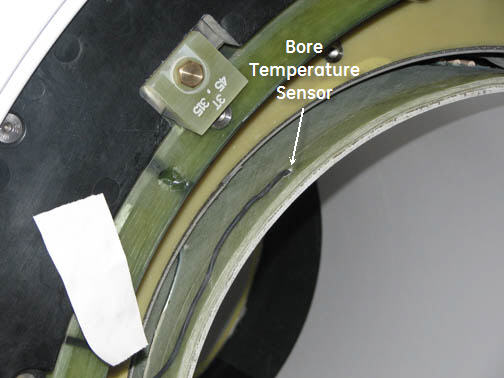
- Insert the bore temperature sensor into the port in the RF body
coil and secure it with tape.
Figure 5. RF body coil port 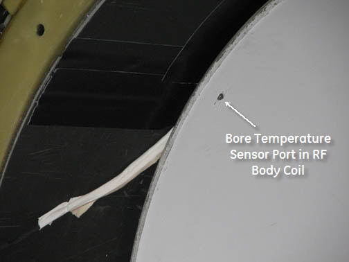
Finalization
Finalization
- Remove LOTO from the PEN cabinet. See the MR Service Safety Manual, PN 5452735.
- Perform a quick head and body scan to ensure that the system is functioning properly.