
- 00000018WIA307BF030GYZ
- id_123746251.4
- Jul 5, 2019 6:08:29 PM
Main Cradle Latch Mechanism Replacements
Prerequisites
| Required persons | Preliminary requirements | Procedure | Finalization |
|---|---|---|---|
| 1 | Not Applicable | 50 minutes | - |
| Item | Quantity | Effectivity | Part number | Manufacturer |
|---|---|---|---|---|
| Non-Magnetic Service Tool Kit | 1 | - |
5112581 | - |
| Item | Quantity | Effectivity | Part number | Manufacturer |
|---|---|---|---|---|
| Cradle Latch Cable (cut to 1500 mm in length) | 1 | - |
Refer to FRU Manual | - |
| Cradle Latch Housing | 1 | - |
Refer to FRU Manual | - |
Procedure
- Lower the Table Lock Safety Bar. Lower the Table and verify
that all weight is resting on the lock bar.
Figure 1. Table Lock Safety Bar 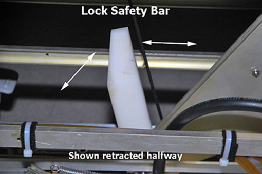
- Manually slide the cradle forward and prop up. For more information,
refer to the Removing Cradle Assembly procedure.
Figure 2. Propping Up the Cradle 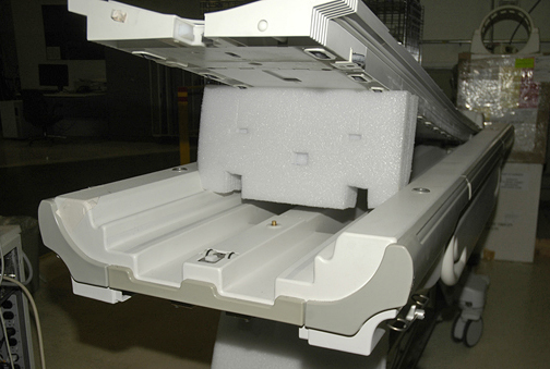
- Using an 5/64 Allen wrench, loosen set screw at Down Link Clevis.
Figure 3. Down Link Clevis 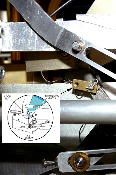
- Remove Patient Table Bottom Cover Front.
Figure 4. Patient Table Bottom Cover Front 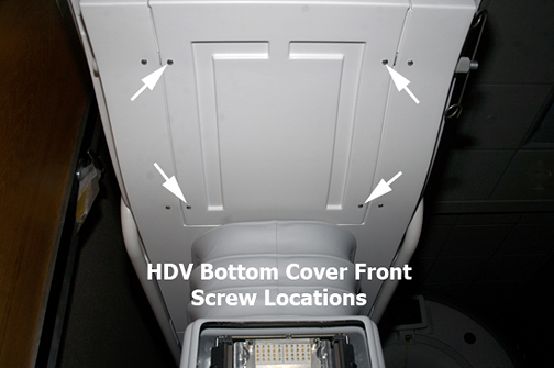
Remove four bolts securing cradle latch housing and cradle latch cover.CAUTION Figure 5. Cradle Latch Housing Bolts 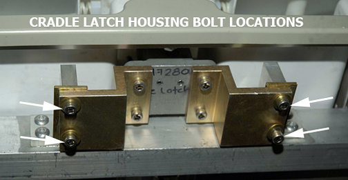
- Pull cable out of Cradle Latch Block on front of Patient Table.
Figure 6. Interlock Cable and Main Cradle Latch Cable Routing 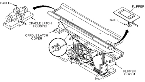
- Insert new cable through head of Cradle Latch Block so once
fully threaded, the swaged end fits into hole in latch pin.
Figure 7. Installing Main Cradle Latch Cable 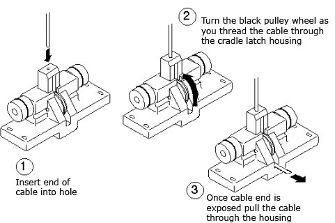
- Loop cable twice through hole in Down Link Clevis.
Figure 8. Cable Path through Down Link Clevis 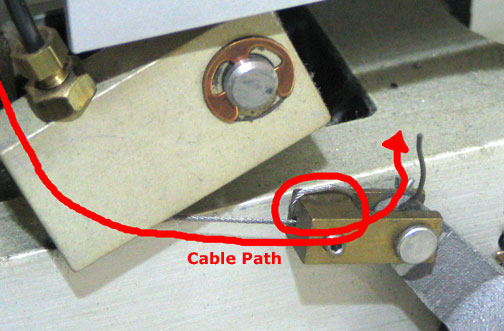
- Loop the excess cable multiple times to bundle itself. See Figure 9.
Figure 9. Bundling the Excess Cabling 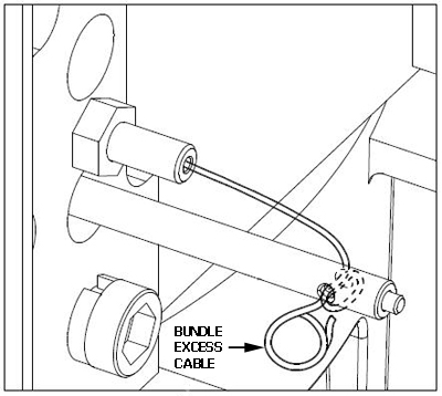
Finalization
Verify proper operation of latching interlock.