- 00000018WIA30E3F030GYZ
- id_123738621.17
- Sep 15, 2020 1:30:23 PM
LPCA Components Replacement
Prerequisites
| Required persons | Preliminary requirements | Procedure | Finalization |
|---|---|---|---|
| 1 | Not Applicable | See Procedure Overview | 20 minutes |
| Item | Quantity | Effectivity | Part number | Manufacturer |
|---|---|---|---|---|
| Non-magnetic service tool kit | 1 | - |
5112581 | - |
| Item | Quantity | Effectivity | Part number | Manufacturer |
|---|---|---|---|---|
| DVMR LPCA (multiple) | 1 each | - |
See FRU manual | - |
| LPCA cover (RRx systems) | 1 each | - |
See FRU manual | - |
| A-port bezel (RRx systems) | 1 each | - |
See FRU manual | - |
| LED and switch harness (RRx systems) | 1 each | - |
See FRU manual | - |
| Sub-D plate | 1 each | - |
See FRU manual | - |
| Plunger assembly | 1 each | - |
See FRU manual | - |
| Cradle latch | 1 each | - |
See FRU manual | - |
| ||||||||
About this task
Overview
LPCA FRU procedures and timings:
-
LPCA cover: procedure timing - 10 minutes
-
A-port bezel: procedure timing - 30 minutes
-
LED and switch harness: procedure timing - 20 minutes
-
Cradle latch: procedure timing - 15 minutes
-
Sub-D plate: procedure timing - 45 minutes
-
Plunger: procedure timing - 15 minutes
Removing and Replacing the LPCA Cover
Procedure
- Remove the four screws on the top of the LPCA cover.
Figure 1. LPCA Cover Screws 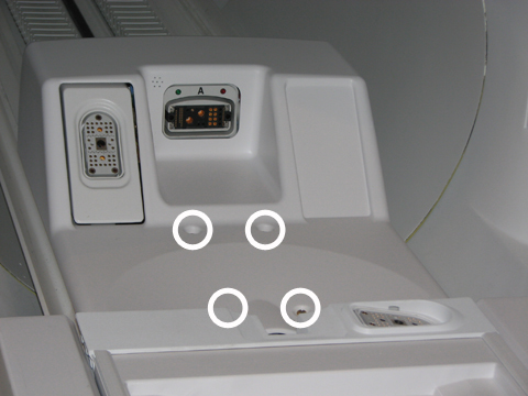
- Re-dock the patient table to drive the LPCA to the home position
and reattach to the cradle/patient table. Dock the table by pressing
the mechanical docking pedal. If the table is equipped with P-connectors
or the GEM coil, engage the electrical dock connector by pressing
the middle foot pedal.
Figure 2. Electronic Docking Pedal 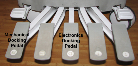
A-Port Bezel
Removing A-Port Bezel
Procedure
Behind the A-port bezel, disconnect all cable connections (J1, J2, J4, and J5) from the sub-D (or bulkhead) plate. A 3/16 nut driver is required to remove J1 and J2.Notice Figure 3. A-Port Bezel Cables 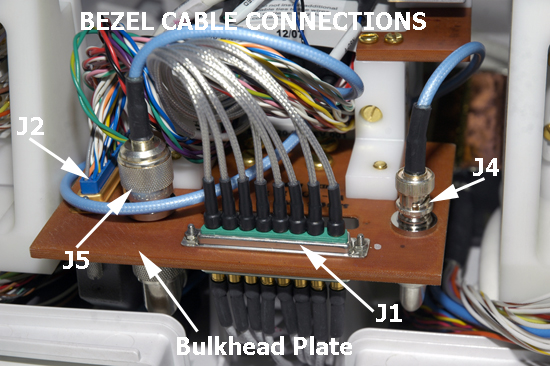
- To remove the microphone cable, pull out the silver block attached
to the end of the microphone cable from behind the microphone bracket.
Figure 4. Microphone Cable Path 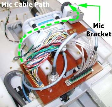
- Remove the LEDs from the bezel. Be careful not to disconnect
the cable from the LEDs.
Figure 5. Removing LED from LED and Switch Harness 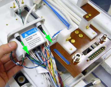 Note:
Note:Reuse the LEDs from the old A-port bezel.
- To remove the A-port bezel from the sub-D plate, remove two
brass pan head screws (left and right) from the plate bracket at the
rear of the A-port bezel.
Figure 6. A-Port Bezel Screws 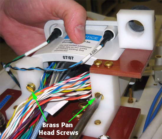
Replacing A-Port Bezel
Procedure
To replace the LED into the socket of the new A-port bezel, use a small slotted screwdriver to push the LED into place, making sure the LED is flush with the face of the bezel.DANGER Figure 7. A-Port Bezel LED Connections 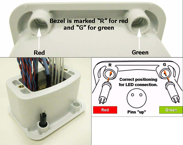
- To properly reconnect all cables, do the following:
- Spread the two sections of wire on J2 and feed J1 though the
separation.
Figure 8. Bezel Cable Routing – substep a 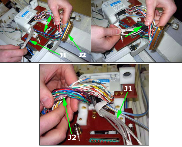
- Leave J1 lying straight out, then rotate J2 counter-clockwise
as needed until it meets up properly with J2 through the sub-D plate.
Push the two connectors together and then secure them using 3/16 inch
nuts and a 3/16 inch nut driver.
Figure 9. Bezel Cable Routing – substep b 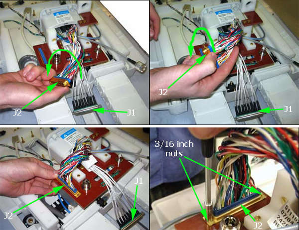
- Connect J5 to the N bulkhead adapter on the sub-D plate.
Figure 10. Bezel Cable Routing – substep c 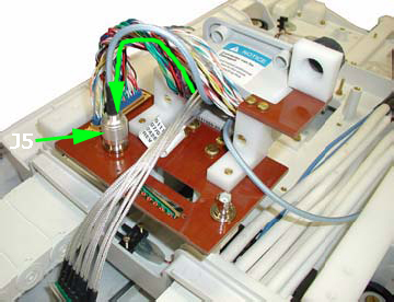
- Connect J1 to J1, through the sub-D plate. Push the two connectors
together and then secure them using 3/16 inch nuts and a 3/16 inch
nut driver.
Figure 11. Bezel Cable Routing – substep d 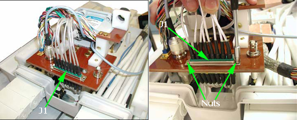
- Feed J4 between J1 and J5. Then wrap J4 around the front of
the sub-D plate, ensuring that it routes below the bezel. Connect
J4 to the BNC bulkhead adapter on the top of the sub-D plate.
Figure 12. Bezel Cable Routing – substep e 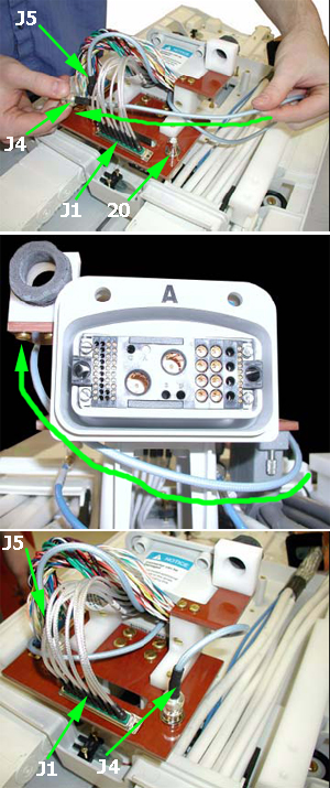
- Spread the two sections of wire on J2 and feed J1 though the
separation.
Removing and Replacing LED and Switch Harness
About this task
Systems using the RRx receive chain have both the LED and switch harness.
Procedure
- Remove the LPCA cover (see Removing and Replacing the LPCA Cover).
Figure 13. Front of LPCA, LED and Switch Harness Connection Points – RRx Receive Chain 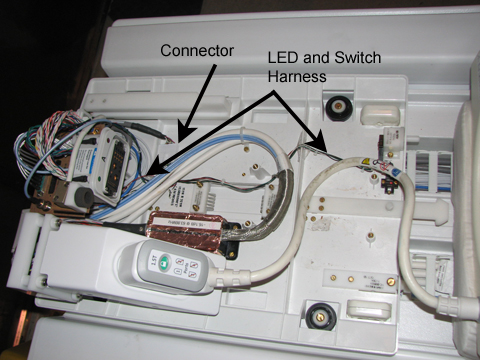
Figure 14. Front of LPCA, Switch Harness Connection Points – DPP Receive Chain 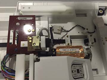
- In the middle of the LPCA near the drive belt well, disconnect the LED and switch harness from the cable track A connection.Note:The LPCA of DPP systems will not have the following items: the bottom balum, a second P-port, and the bezel.
Figure 15. LPCA Rear-DPP Receive Chain 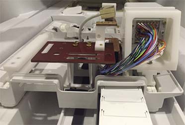
- At the rear of the LPCA, remove the LEDs from the top of the A-port bezel. Be careful not to disconnect the cable from the LEDs.
Figure 16. Rear of LPCA and Switch Harness Connection Points – RRx Receive Chain 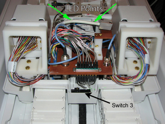
- Remove all screws holding all three switches.
Switches 1 and 2 are on the front of the LPCA, and switch 3 is in the rear of the LPCA.
Figure 17. Switch Locations 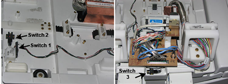
Removing and Replacing Cradle Latch
Procedure
- Remove the four brass slotted head screws at the base of the
cradle latch.
Figure 18. LPCA Cradle Latch 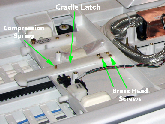
Removing and Replacing Sub-D (or Bulkhead) Plate
About this task
The sub-D plate contains two components on systems using the RRx receive chain (the A-port bezel and the microphone). To replace the sub-D plate, both components and their respective cable connections must be completely removed.
Procedure
- On the replacement sub-D plate, reattach cable connections and
bulkhead adapters on the bottom of the plate.
Figure 19. Bottom of Sub-D (or Bulkhead) Plate 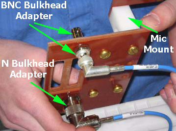
- To reattach the sub-D plate to the LPCA assembly, do the following:
- Leave the microphone cable (silver cable block) lying straight,
making sure that it is on top of J1, J4, and J5 and not connected.
Figure 20. Reattaching Sub-D Plate and J2 Connector 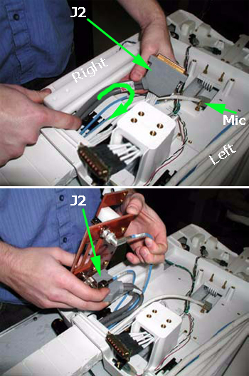
- Leave the microphone cable (silver cable block) lying straight,
making sure that it is on top of J1, J4, and J5 and not connected.
Removing and Replacing Plunger Assembly
Procedure
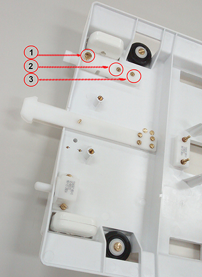
- Remove the three screws securing the plunger assembly to the
LPCA base (1,2,3) and remove the plunger assembly.
Figure 21. LPCA Plunger Assembly